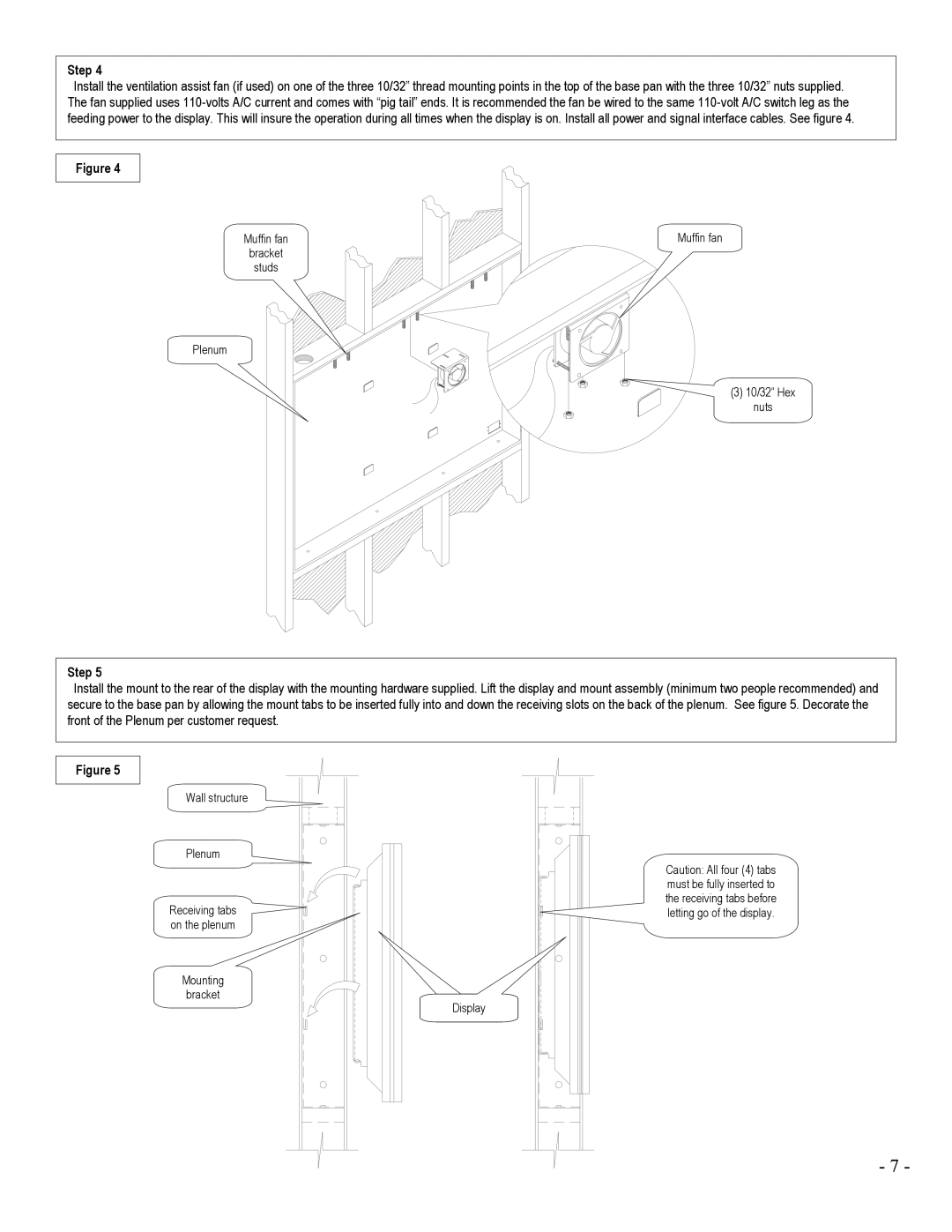
Step 4
Install the ventilation assist fan (if used) on one of the three 10/32” thread mounting points in the top of the base pan with the three 10/32” nuts supplied. The fan supplied uses
Figure 4
Muffin fan | Muffin fan |
bracket |
|
studs |
|
Plenum
(3) 10/32” Hex
nuts
Step 5
Install the mount to the rear of the display with the mounting hardware supplied. Lift the display and mount assembly (minimum two people recommended) and secure to the base pan by allowing the mount tabs to be inserted fully into and down the receiving slots on the back of the plenum. See figure 5. Decorate the front of the Plenum per customer request.
Figure 5
Wall structure
Plenum
Receiving tabs on the plenum
Mounting
bracket
Display
Caution: All four (4) tabs must be fully inserted to the receiving tabs before letting go of the display.
- 7 -
