CONTROLS AND CONNECTIONS
3.3 BACK PANEL LAYOUT
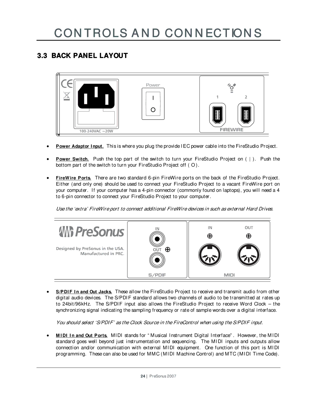
•Power Adaptor Input. This is where you plug the provide IEC power cable into the FireStudio Project.
•Power Switch. Push the top part of the switch to turn your FireStudio Project on ( ). Push the bottom part of the switch to turn your FireStudio Project off ( O ).
•FireWire Ports. There are two standard
Use the ‘extra’ FireWire port to connect additional FireWire devices in such as external Hard Drives.
•S/PDIF In and Out Jacks. These allow the FireStudio Project to receive and transmit audio from other digital audio devices. The S/PDIF standard allows two channels of audio to be transmitted at rates up to 24bit/96kHz. The S/PDIF input also allows the FireStudio Project to receive Word Clock – the synchronizing signal indicating the sampling frequency or rate of sample words over a digital interface.
You should select ‘S/PDIF’ as the Clock Source in the FireControl when using the S/PDIF input.
•MIDI In and Out Ports. MIDI stands for “Musical Instrument Digital Interface”. However, the MIDI standard goes well beyond just instrumentation and sequencing. The MIDI inputs and outputs allow connection and/or communication with external MIDI equipment. One function of this port is MIDI programming. These can also be used for MMC (MIDI Machine Control) and MTC (MIDI Time Code).
24 PreSonus 2007