I I I . Y O U R P O W E R C H A I R |
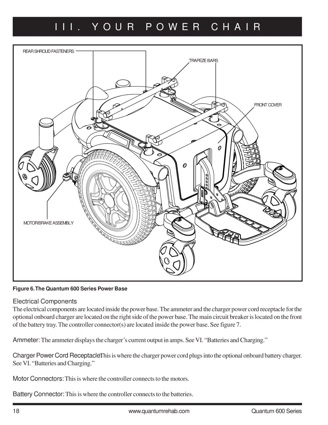
REAR SHROUD FASTENERS |
TRAPEZE BARS |
FRONT COVER |
MOTOR/BRAKE ASSEMBLY |
Figure 6.The Quantum 600 Series Power Base
Electrical Components
The electrical components are located inside the power base. The ammeter and the charger power cord receptacle for the optional onboard charger are located on the right side of the power base. The main circuit breaker is located on the front of the battery tray. The controller connector(s) are located inside the power base. See figure 7.
Ammeter: The ammeter displays the charger’s current output in amps. See VI. “Batteries and Charging.”
Charger Power Cord Receptacle: This is where the charger power cord plugs into the optional onboard battery charger. See VI. “Batteries and Charging.”
Motor Connectors: This is where the controller connects to the motors.
Battery Connector: This is where the controller connects to the batteries.
18 | www.quantumrehab.com | Quantum 600 Series |