V . Y O U R P R I D E L X
Electronic Connections
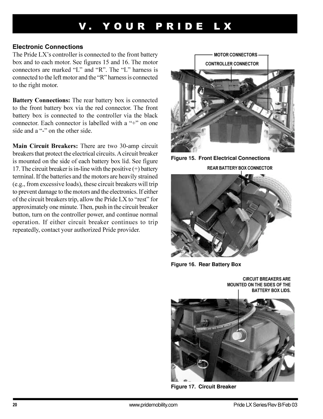
The Pride LX’s controller is connected to the front battery box and to each motor. See figures 15 and 16. The motor connectors are marked “L” and “R”. The “L” harness is connected to the left motor and the “R” harness is connected to the right motor.
Battery Connections: The rear battery box is connected to the front battery box via the red connector. The front battery box is connected to the controller via the black connector. Each connector is labelled with a “+” on one side and a
Main Circuit Breakers: There are two
17.The circuit breaker is
MOTOR CONNECTORS
CONTROLLER CONNECTOR
Figure 15. Front Electrical Connections
REAR BATTERY BOX CONNECTOR
Figure 16. Rear Battery Box
CIRCUIT BREAKERS ARE
MOUNTED ON THE SIDES OF THE
BATTERY BOX LIDS.
Figure 17. Circuit Breaker
20 | www.pridemobility.com | Pride LX Series/Rev B/Feb 03 |