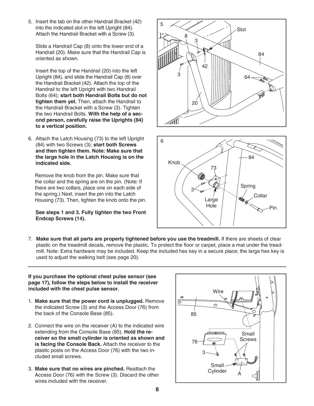
5.Insert the tab on the other Handrail Bracket (42) into the indicated slot in the left Upright (84). Attach the Handrail Bracket with a Screw (3).
Slide a Handrail Cap (8) onto the lower end of a Handrail (20). Make sure that the Handrail Cap is oriented as shown.
Insert the top of the Handrail (20) into the left Upright (84), and slide the Handrail Cap (8) over the Handrail Bracket (42). Attach the top of the Handrail to the left Upright with two Handrail Bolts (64); start both Handrail Bolts but do not tighten them yet. Then, attach the Handrail to the Handrail Bracket with a Screw (3). Tighten the two Handrail Bolts. With the help of a sec- ond person, carefully raise the Uprights (84) to a vertical position.
6.Attach the Latch Housing (73) to the left Upright (84) with two Screws (3); start both Screws and then tighten them. Note: Make sure that the large hole in the Latch Housing is on the indicated side.
Remove the knob from the pin. Make sure that the collar and the spring are on the pin. (Note: If there are two collars, place one on each side of the spring.) Next, insert the pin into the Latch Housing (73). Then, tighten the knob onto the pin.
See steps 1 and 3. Fully tighten the two Front Endcap Screws (14).
5 | Slot |
| |
| 8 |
| 3 |
| 84 |
| 42 |
3 | 64 |
| |
| 20 |
6 |
|
Knob | 84 |
| |
73 |
|
3 | Spring |
| |
Large | Collar |
| |
Hole | Pin |
|
7.Make sure that all parts are properly tightened before you use the treadmill. If there are sheets of clear plastic on the treadmill decals, remove the plastic. To protect the floor or carpet, place a mat under the tread- mill. Note: Extra hardware may be included. Keep the included hex key in a secure place; the large hex key is used to adjust the walking belt (see page 20).
If you purchase the optional chest pulse sensor (see page 17), follow the steps below to install the receiver included with the chest pulse sensor.
1.Make sure that the power cord is unplugged. Remove the indicated Screw (3) and the Access Door (76) from the back of the Console Base (85).
2.Connect the wire on the receiver (A) to the indicated wire extending from the Console Base (85). Hold the re- ceiver so the small cylinder is oriented as shown and is facing the Console Back. Attach the receiver to the plastic posts on the Access Door (76) with the two in- cluded small screws.
3.Make sure that no wires are pinched. Reattach the Access Door (76) with the Screw (3). Discard the other wires included with the receiver.
| Wire |
|
85 |
|
|
|
| Small |
76 |
| Screws |
|
| |
| 3 |
|
| Small |
|
| Cylinder | A |
|
|
8