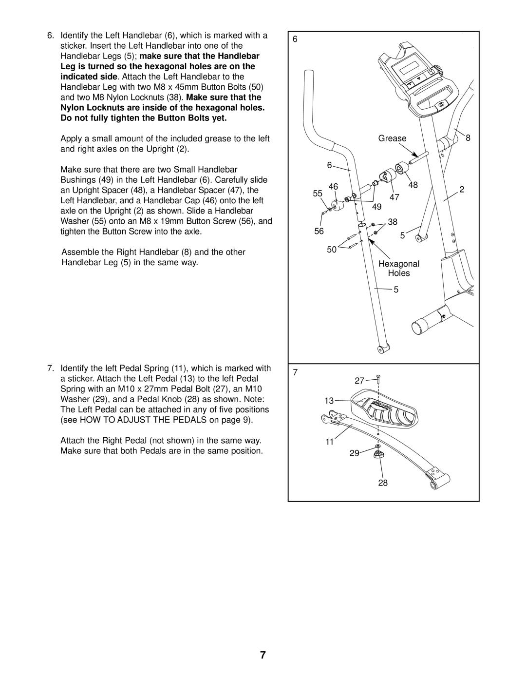
6.Identify the Left Handlebar (6), which is marked with a sticker. Insert the Left Handlebar into one of the
Handlebar Legs (5); | make sure that the Handlebar |
| ||
Leg is turned so the hexagonal holes are on the |
| |||
indicated side | . Attach the Left Handlebar to the |
| ||
Handlebar Leg with two M8 x | 45mm Button Bolts (50) | |||
and two M8 Nylon Locknuts (38). | Make sure that the | |||
Nylon Locknuts are inside of the hexagonal holes. |
| |||
Do not fully tighten the Button Bolts yet. |
|
| ||
Apply a small amount of the included grease to the left |
| |||
and right axles on the Upright (2). |
|
| ||
Make sure that there are two Small Handlebar |
|
| ||
Bushings (49) in the Left Handlebar (6). C | arefully slide | |||
an Upright Spacer (48), a Handlebar Spacer (47), the |
| |||
Left Handlebar, and a Handlebar Cap (46) onto the left |
| |||
axle on the Upright (2) as shown. Slide a Handlebar |
| |||
Washer (55) onto an M8 x 19mm Button Screw (56), and |
| |||
tighten the Button Screw into the axle. |
|
| ||
Assemble the Right Handlebar (8) and the other
Handlebar Leg (5) in the same way.
7.Identify the left Pedal Spring (11), which is marked with a sticker. Attach the Left Pedal (13) to the left Pedal Spring with an M10 x 27mm Pedal Bolt (27), an M10 Washer (29), and a Pedal Knob (28) as shown. Note: The Left Pedal can be attached in any of five positions
(see HOW TO ADJUST THE PEDALS on page 9).
Attach the Right Pedal (not shown) in the same way.
Make sure that both Pedals are in the same position.
6 |
|
|
|
| Grease |
| 8 |
| 6 |
|
|
55 | 46 | 48 | 2 |
47 |
| ||
|
| ||
|
|
| |
| 49 |
|
|
56 | 38 |
|
|
5 |
|
| |
|
|
| |
| 50 |
|
|
| Hexagonal |
|
|
| Holes |
|
|
| 5 |
|
|
7 | 27 |
|
|
|
|
| |
| 13 |
|
|
| 11 |
|
|
| 29 |
|
|
| 28 |
|
|
7
