ASSEMBLY
Place all parts of the stepper in a cleared area and remove the packing materials. Do not dispose of the packing
materials until assembly is completed. Assembly requires the included allen wrench ![]() , a phillips
, a phillips
screwdriver ![]()
![]() , two adjustable wrenches
, two adjustable wrenches ![]() and a rubber mallet
and a rubber mallet ![]() .
.
PART CHART
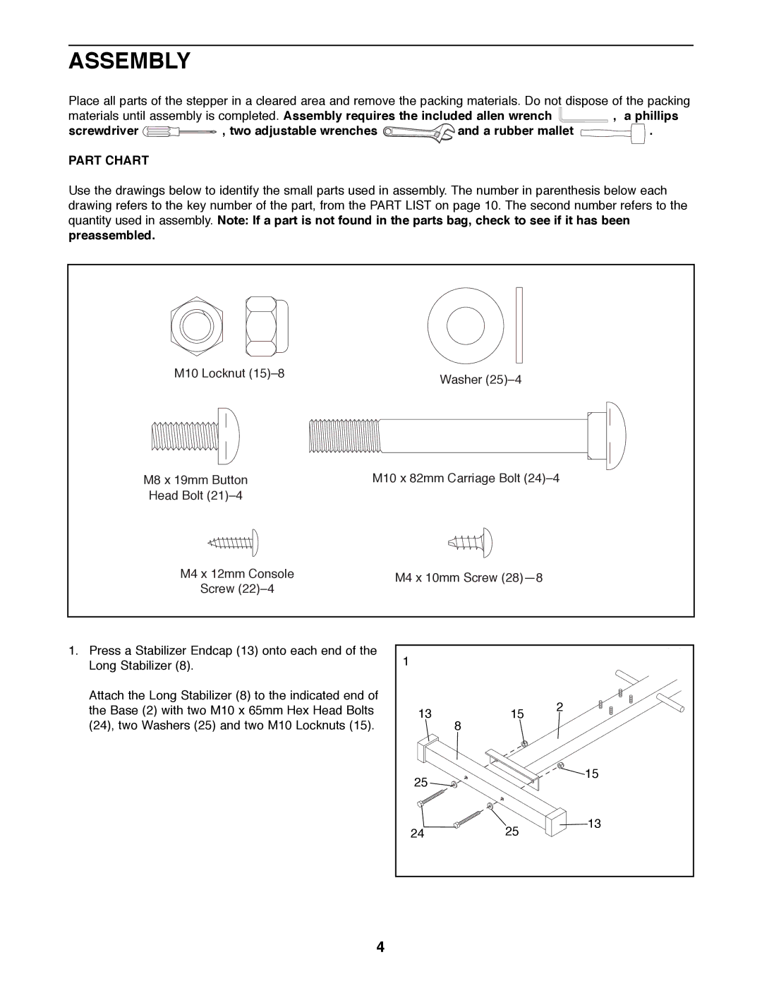
Use the drawings below to identify the small parts used in assembly. The number in parenthesis below each drawing refers to the key number of the part, from the PART LIST on page 10. The second number refers to the quantity used in assembly. Note: If a part is not found in the parts bag, check to see if it has been preassembled.
M10 Locknut (15)Ð8 | Washer (25)Ð4 |
|
M8 x 19mm Button | M10 x 82mm Carriage Bolt (24)Ð4 |
Head Bolt (21)Ð4 |
|
M4 x 12mm Console | M4 x 10mm Screw (28)Ñ8 |
| |
Screw (22)Ð4 |
| ||
|
|
| |
1. Press a Stabilizer Endcap (13) onto each end of the | 1 |
|
|
Long Stabilizer (8). |
|
| |
|
|
| |
Attach the Long Stabilizer (8) to the indicated end of |
|
| 2 |
the Base (2) with two M10 x 65mm Hex Head Bolts | 13 | 15 | |
(24), two Washers (25) and two M10 Locknuts (15). |
| 8 |
|
| 25 |
| 15 |
|
|
| |
| 24 | 25 | 13 |
|
| ||
4