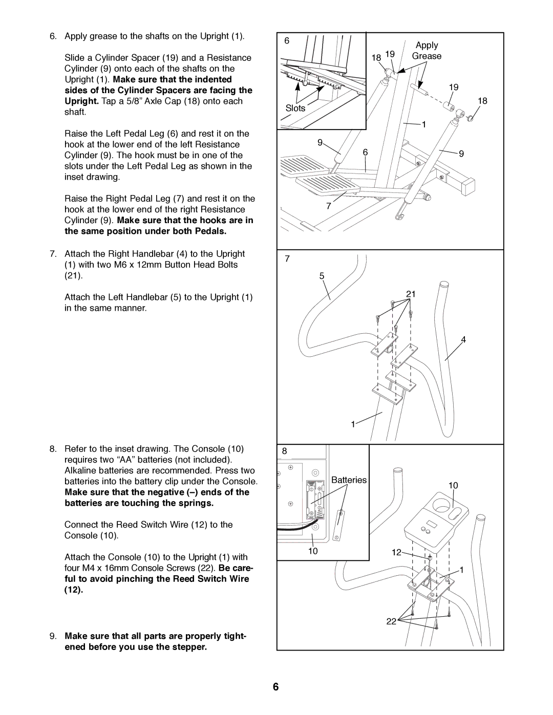
6. Apply grease to the shafts on the Upright (1). | 6 |
| Apply |
|
| ||
|
| 18 19 | |
Slide a Cylinder Spacer (19) and a Resistance |
| Grease | |
Cylinder (9) onto each of the shafts on the |
|
|
|
Upright (1). Make sure that the indented |
|
| 19 |
sides of the Cylinder Spacers are facing the |
|
| |
|
|
| |
Upright. Tap a 5/8Ó Axle Cap (18) onto each | Slots |
| 18 |
shaft. |
|
| |
|
|
| |
Raise the Left Pedal Leg (6) and rest it on the |
|
| 1 |
9 |
|
| |
hook at the lower end of the left Resistance |
|
| |
Cylinder (9). The hook must be in one of the | 6 |
| 9 |
slots under the Left Pedal Leg as shown in the |
|
|
|
inset drawing. |
|
|
|
Raise the Right Pedal Leg (7) and rest it on the | 7 |
|
|
hook at the lower end of the right Resistance |
|
| |
|
|
| |
Cylinder (9). Make sure that the hooks are in |
|
|
|
the same position under both Pedals. |
|
|
|
7. Attach the Right Handlebar (4) to the Upright | 7 |
|
|
(1) with two M6 x 12mm Button Head Bolts |
|
| |
|
|
| |
(21). | 5 |
|
|
Attach the Left Handlebar (5) to the Upright (1) |
|
| 21 |
|
|
| |
in the same manner. |
|
|
|
|
|
| 4 |
| 1 |
|
|
8. Refer to the inset drawing. The Console (10) | 8 |
|
|
requires two ÒAAÓ batteries (not included). |
|
|
|
Alkaline batteries are recommended. Press two | Batteries |
|
|
batteries into the battery clip under the Console. |
| 10 | |
Make sure that the negative (Ð) ends of the |
|
| |
|
|
| |
batteries are touching the springs. |
|
|
|
Connect the Reed Switch Wire (12) to the |
|
|
|
Console (10). |
|
|
|
Attach the Console (10) to the Upright (1) with | 10 | 12 |
|
|
|
| |
four M4 x 16mm Console Screws (22). Be care- |
|
| 1 |
ful to avoid pinching the Reed Switch Wire |
|
|
|
(12). |
|
|
|
|
| 22 |
|
9. Make sure that all parts are properly tight- |
|
|
|
ened before you use the stepper. |
|
|
|
| 6 |
|
|