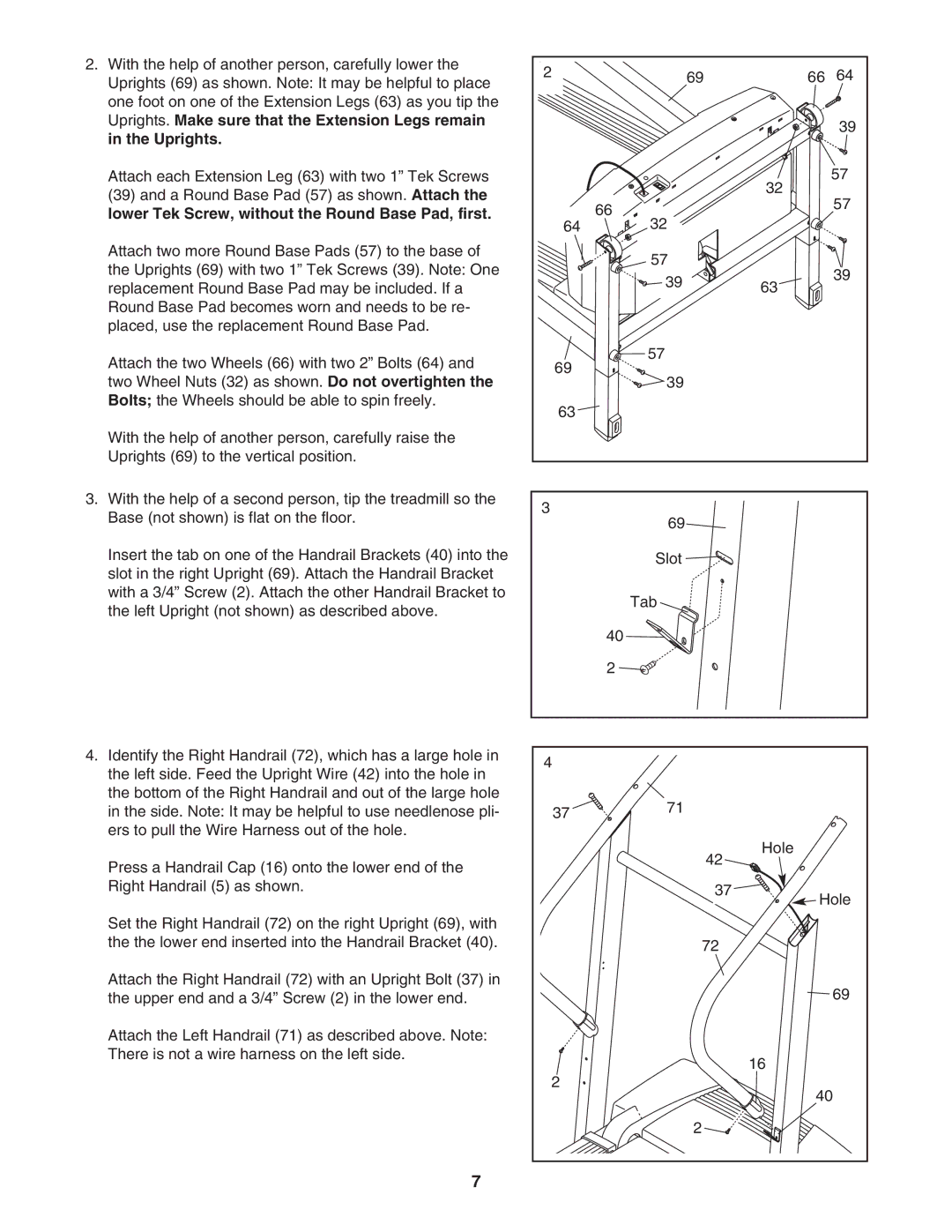
2.With the help of another person, carefully lower the Uprights (69) as shown. Note: It may be helpful to place one foot on one of the Extension Legs (63) as you tip the Uprights. Make sure that the Extension Legs remain in the Uprights.
Attach each Extension Leg (63) with two 1” Tek Screws
(39)and a Round Base Pad (57) as shown. Attach the lower Tek Screw, without the Round Base Pad, first.
Attach two more Round Base Pads (57) to the base of the Uprights (69) with two 1” Tek Screws (39). Note: One replacement Round Base Pad may be included. If a Round Base Pad becomes worn and needs to be re- placed, use the replacement Round Base Pad.
Attach the two Wheels (66) with two 2” Bolts (64) and two Wheel Nuts (32) as shown. Do not overtighten the Bolts; the Wheels should be able to spin freely.
With the help of another person, carefully raise the Uprights (69) to the vertical position.
3.With the help of a second person, tip the treadmill so the Base (not shown) is flat on the floor.
Insert the tab on one of the Handrail Brackets (40) into the slot in the right Upright (69). Attach the Handrail Bracket with a 3/4” Screw (2). Attach the other Handrail Bracket to the left Upright (not shown) as described above.
4.Identify the Right Handrail (72), which has a large hole in the left side. Feed the Upright Wire (42) into the hole in the bottom of the Right Handrail and out of the large hole in the side. Note: It may be helpful to use needlenose pli- ers to pull the Wire Harness out of the hole.
Press a Handrail Cap (16) onto the lower end of the Right Handrail (5) as shown.
Set the Right Handrail (72) on the right Upright (69), with the the lower end inserted into the Handrail Bracket (40).
Attach the Right Handrail (72) with an Upright Bolt (37) in the upper end and a 3/4” Screw (2) in the lower end.
Attach the Left Handrail (71) as described above. Note: There is not a wire harness on the left side.
7
2 | 69 | 66 | 64 |
|
|
| 39 |
|
| 32 | 57 |
|
| 57 | |
| 66 |
| |
|
|
| |
64 | 32 |
|
|
| 57 |
| 39 |
| 39 | 63 | |
|
| ||
|
|
| |
69 | 57 |
|
|
39 |
|
| |
|
|
| |
63 |
|
|
|
3 | 69 |
|
|
|
|
|
Slot ![]()
![]()
| Tab |
|
| 40 |
|
| 2 |
|
4 |
|
|
37 | 71 |
|
|
| |
| 42 | Hole |
|
| |
| 37 | Hole |
|
| |
| 72 |
|
|
| 69 |
|
| 16 |
2 |
| 40 |
|
| |
| 2 |
|