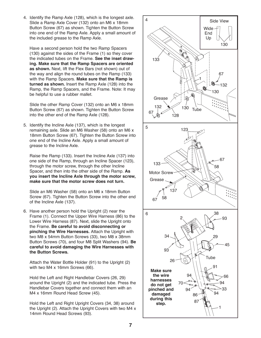
4.Identify the Ramp Axle (128), which is the longest axle. Slide a Ramp Axle Cover (132) onto an M6 x 18mm Button Screw (67) as shown. Tighten the Button Screw into one end of the Ramp Axle. Apply a small amount of the included grease to the Ramp Axle.
Have a second person hold the two Ramp Spacers (130) against the sides of the Frame (1) so they cover the indicated tubes on the Frame. See the inset draw- ing. Make sure that the Ramp Spacers are oriented as shown. Next, lift the Flex Bars (not shown) out of the way and align the round tubes on the Ramp (133) with the Ramp Spacers. Make sure that the Ramp is turned as shown. Insert the Ramp Axle (128) into the Ramp, the Ramp Spacers, and the Frame. Note: It may be helpful to use a rubber mallet.
Slide the other Ramp Cover (132) onto an M6 x 18mm Button Screw (67) as shown. Tighten the Button Screw into the other end of the Ramp Axle (128).
5.Identify the Incline Axle (137), which is the longest remaining axle. Slide an M6 Washer (58) onto an M6 x 18mm Button Screw (67). Tighten the Button Screw into one end of the Incline Axle. Apply a small amount of grease to the Incline Axle.
Raise the Ramp (133). Insert the Incline Axle (137) into one side of the Ramp, through an Incline Spacer (123), through the motor screw, through the other InclineAs Spacer, and then into the other side of the Ramp. you insert the Incline Axle through the motor screw, make sure that the motor screw does not turn. Slide an M6 Washer (58) onto an M6 x 18mm Button Screw (67). Tighten the Button Screw into the other end of the Incline Axle (137).
6.Have another person hold the Upright (2) near the Frame (1). Connect the Upper Wire Harness (86) to the Lower Wire Harness (87). Next, slide the Upright onto the Frame. Be careful to avoid disconnecting or pinching the Wire Harnesses. Attach the Upright with two M8 x 54mm Button Screws (33), two M8 x 38mmBe Button Screws (70), and four M8 Split Washers (94). careful to avoid damaging the Wire Harnesses with the Button Screws.
Attach the Water Bottle Holder (91) to the Upright (2) with two M4 x 16mm Screws (66).
Hold the Left and Right Handlebar Covers (26, 29) around the Upright (2) and the indicated tube. Press the Handlebar Covers together and connect them with an M4 x 16mm Round Head Screw (45).
Hold the Left and Right Upright Covers (34, 38) around the Upright (2). Attach the Upright Covers with two M4 x 14mm Round Head Screws (93).
7
4 |
|
|
| Side View | |
|
|
|
| Wide |
|
|
|
|
| End |
|
|
|
|
| Up | 130 |
|
|
|
|
| |
133 |
|
|
|
|
|
|
|
| 1 | 67 | |
|
|
|
| 132 | |
Grease |
|
|
| 130 | |
|
|
|
|
| |
67 132 | 128 | 130 | Tube |
|
|
5 |
|
|
|
| |
| 123 |
|
|
| |
133 |
|
|
|
|
| 58 67 | |
Motor Screw |
|
|
|
|
| ||
Grease | 137 |
|
|
|
|
| |
67 | 58 |
|
|
|
|
| |
6 |
|
| 2 |
|
| 38 | 93 |
| 34 |
|
|
|
| 29 | 45 |
| 93 |
|
|
|
|
| |
| 26 |
|
|
| Tube |
| |
|
|
|
|
|
| ||
Make sure |
| 94 |
| 91 | 66 | ||
the wire |
|
|
|
| |||
harnesses | 70 |
|
|
| 94 | ||
do not get | 94 |
|
| ||||
pinched and |
| 86 | 94 | 33 | |||
damaged |
|
|
| ||||
during this |
|
| 87 |
|
| ||
step. |
|
|
|
| 1 | ||
|
|
|
|
|
|
| |