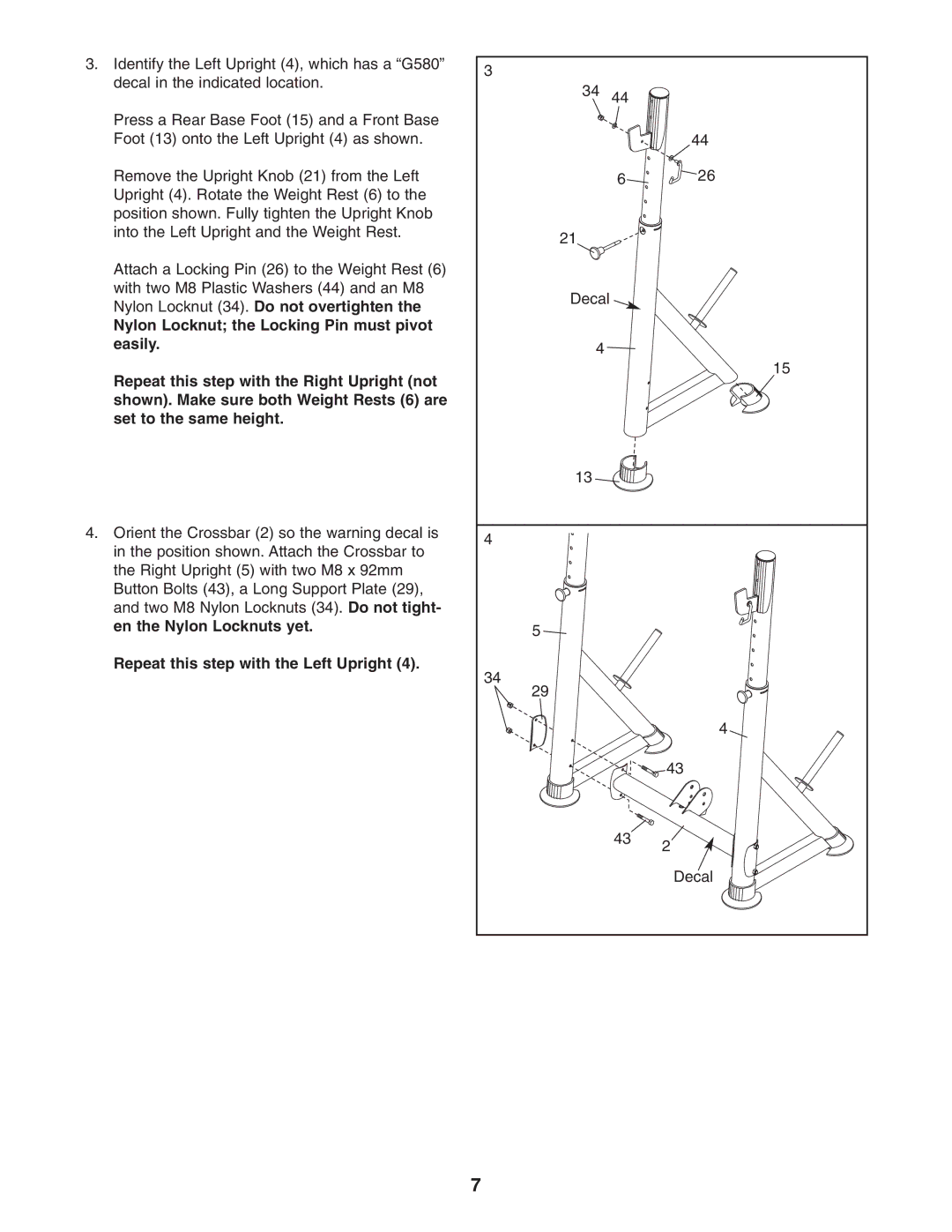
3. Identify the Left Upright (4), which has a “G580” | 3 |
|
|
decal in the indicated location. |
|
| |
34 | 44 |
| |
|
| ||
Press a Rear Base Foot (15) and a Front Base |
|
|
|
Foot (13) onto the Left Upright (4) as shown. |
|
| 44 |
Remove the Upright Knob (21) from the Left |
| 6 | 26 |
Upright (4). Rotate the Weight Rest (6) to the |
|
|
|
position shown. Fully tighten the Upright Knob |
|
|
|
into the Left Upright and the Weight Rest. | 21 |
|
|
|
|
| |
Attach a Locking Pin (26) to the Weight Rest (6) |
|
|
|
with two M8 Plastic Washers (44) and an M8 | Decal |
|
|
Nylon Locknut (34). Do not overtighten the |
|
| |
|
|
| |
Nylon Locknut; the Locking Pin must pivot |
|
|
|
easily. | 4 |
|
|
|
|
| |
Repeat this step with the Right Upright (not |
|
| 15 |
|
|
| |
shown). Make sure both Weight Rests (6) are |
|
|
|
set to the same height. |
|
|
|
| 13 |
|
|
4. Orient the Crossbar (2) so the warning decal is | 4 |
|
|
in the position shown. Attach the Crossbar to |
|
| |
|
|
| |
the Right Upright (5) with two M8 x 92mm |
|
|
|
Button Bolts (43), a Long Support Plate (29), |
|
|
|
and two M8 Nylon Locknuts (34). Do not tight- |
|
|
|
en the Nylon Locknuts yet. | 5 |
|
|
|
|
| |
Repeat this step with the Left Upright (4). | 34 |
|
|
|
|
| |
| 29 |
|
|
|
|
| 4 |
|
|
| 43 |
|
| 43 | 2 |
|
|
| |
|
|
| Decal |
| 7 |
|
|
