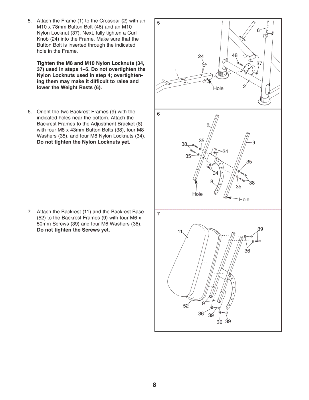
5. Attach the Frame (1) to the Crossbar (2) with an | 5 |
|
|
M10 x 78mm Button Bolt (48) and an M10 |
|
| |
|
| 6 | |
Nylon Locknut (37). Next, fully tighten a Curl |
|
| |
|
|
| |
Knob (24) into the Frame. Make sure that the |
|
|
|
Button Bolt is inserted through the indicated |
|
|
|
hole in the Frame. | 24 |
| 48 |
|
| ||
Tighten the M8 and M10 Nylon Locknuts (34, |
|
| 37 |
37) used in steps | 1 |
|
|
Nylon Locknuts used in step 4; overtighten- |
|
| |
|
|
| |
ing them may make it difficult to raise and |
|
| 2 |
lower the Weight Rests (6). |
| Hole | |
6. Orient the two Backrest Frames (9) with the | 6 |
|
|
indicated holes near the bottom. Attach the |
|
| |
|
|
| |
Backrest Frames to the Adjustment Bracket (8) |
| 9 |
|
with four M8 x 43mm Button Bolts (38), four M8 |
|
|
|
Washers (35), and four M8 Nylon Locknuts (34). | 35 |
|
|
Do not tighten the Nylon Locknuts yet. |
| 9 | |
| 38 |
|
|
| 35 | 34 |
|
|
| 35 | |
|
|
| |
|
| 34 |
|
|
| 8 | 38 |
|
|
| 35 |
| Hole |
| Hole |
|
|
| |
7. Attach the Backrest (11) and the Backrest Base | 7 |
|
|
(52) to the Backrest Frames (9) with four M6 x |
|
| |
|
|
| |
50mm Screws (39) and four M6 Washers (36). |
|
| 39 |
Do not tighten the Screws yet. | 11 |
| |
|
|
| |
|
|
| 36 |
52 9
36 39 ![]()
![]()
![]()
![]()
![]()
![]() 36 39
36 39
8
