MODEL | SECTION 10.0 |
| DIAGNOSIS AND TROUBLESHOOTING |
10.8TROUBLESHOOTING WHEN A FAULT OR WARNING MESSAGE IS SHOWING
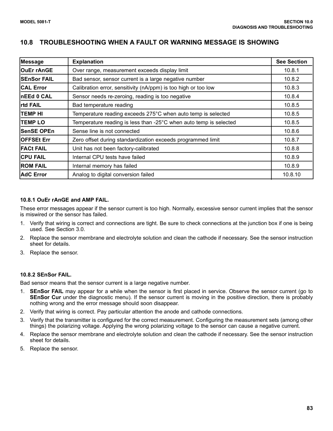
| Message | Explanation | See Section |
|
|
|
|
|
|
| OuEr rAnGE | Over range, measurement exceeds display limit | 10.8.1 |
|
|
|
|
|
|
| SEnSor FAIL | Bad sensor, sensor current is a large negative number | 10.8.2 |
|
|
|
|
|
|
| CAL Error | Calibration error, sensitivity (nA/ppm) is too high or too low | 10.8.3 |
|
|
|
|
|
|
| nEEd 0 CAL | Sensor needs | 10.8.4 |
|
|
|
|
|
|
| rtd FAIL | Bad temperature reading | 10.8.5 |
|
| TEMP HI | Temperature reading exceeds 275°C when auto temp is selected | 10.8.5 |
|
|
|
|
|
|
| TEMP LO | Temperature reading is less than | 10.8.5 |
|
|
|
|
|
|
| SenSE OPEn | Sense line is not connected | 10.8.6 |
|
| OFFSEt Err | Zero offset during standardization exceeds programmed limit | 10.8.7 |
|
|
|
|
|
|
| FACt FAIL | Unit has not been | 10.8.8 |
|
|
|
|
|
|
| CPU FAIL | Internal CPU tests have failed | 10.8.9 |
|
|
|
|
|
|
| ROM FAIL | Internal memory has failed | 10.8.9 |
|
| AdC Error | Analog to digital conversion failed | 10.8.10 |
|
|
|
|
|
|
|
|
|
|
|
10.8.1 OuEr rAnGE and AMP FAIL.
These error messages appear if the sensor current is too high. Normally, excessive sensor current implies that the sensor is miswired or the sensor has failed.
1.Verify that wiring is correct and connections are tight. Be sure to check connections at the junction box if one is being used. See Section 3.0.
2.Replace the sensor membrane and electrolyte solution and clean the cathode if necessary. See the sensor instruction sheet for details.
3.Replace the sensor.
10.8.2 SEnSor FAIL.
Bad sensor means that the sensor current is a large negative number.
1.SEnSor FAIL may appear for a while when the sensor is first placed in service. Observe the sensor current (go to SEnSor Cur under the diagnostic menu). If the sensor current is moving in the positive direction, there is probably nothing wrong and the error message should soon disappear.
2.Verify that wiring is correct. Pay particular attention the anode and cathode connections.
3.Verify that the transmitter is configured for the correct measurement. Configuring the measurement sets (among other things) the polarizing voltage. Applying the wrong polarizing voltage to the sensor can cause a negative current.
4.Replace the sensor membrane and electrolyte solution and clean the cathode if necessary. See the sensor instruction sheet for details.
5.Replace the sensor.
83
