MODEL | SECTION 11.0 |
| MAINTENANCE |
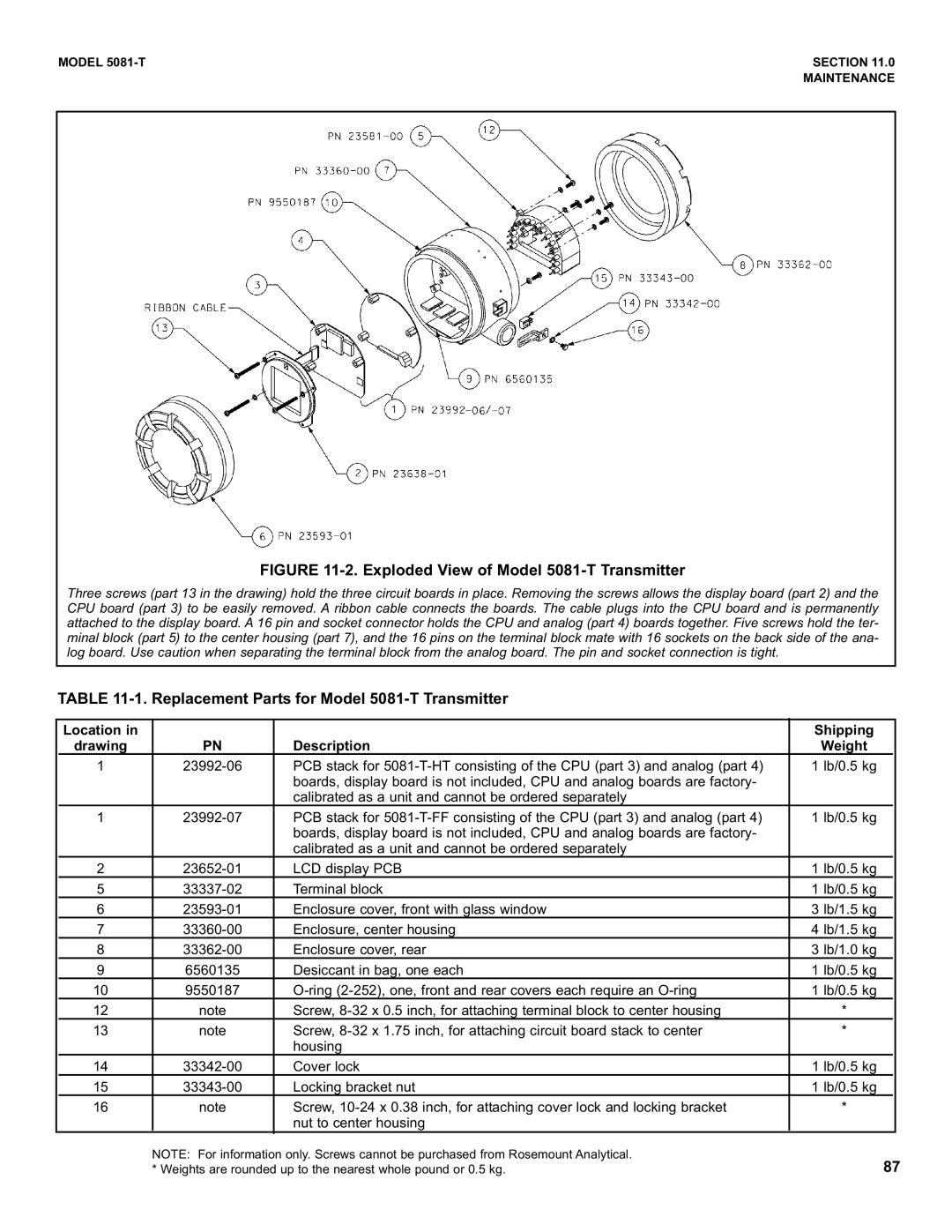
FIGURE 11-2. Exploded View of Model 5081-T Transmitter
Three screws (part 13 in the drawing) hold the three circuit boards in place. Removing the screws allows the display board (part 2) and the CPU board (part 3) to be easily removed. A ribbon cable connects the boards. The cable plugs into the CPU board and is permanently attached to the display board. A 16 pin and socket connector holds the CPU and analog (part 4) boards together. Five screws hold the ter- minal block (part 5) to the center housing (part 7), and the 16 pins on the terminal block mate with 16 sockets on the back side of the ana- log board. Use caution when separating the terminal block from the analog board. The pin and socket connection is tight.
TABLE 11-1. Replacement Parts for Model 5081-T Transmitter
| Location in |
|
| Shipping |
|
| drawing | PN | Description | Weight |
|
| 1 | PCB stack for | 1 lb/0.5 kg |
| |
|
|
| boards, display board is not included, CPU and analog boards are factory- |
|
|
|
|
| calibrated as a unit and cannot be ordered separately |
|
|
| 1 | PCB stack for | 1 lb/0.5 kg |
| |
|
|
| boards, display board is not included, CPU and analog boards are factory- |
|
|
|
|
| calibrated as a unit and cannot be ordered separately |
|
|
| 2 | LCD display PCB | 1 lb/0.5 kg |
| |
| 5 | Terminal block | 1 lb/0.5 kg |
| |
| 6 | Enclosure cover, front with glass window | 3 lb/1.5 kg |
| |
| 7 | Enclosure, center housing | 4 lb/1.5 kg |
| |
| 8 | Enclosure cover, rear | 3 lb/1.0 kg |
| |
| 9 | 6560135 | Desiccant in bag, one each | 1 lb/0.5 kg |
|
| 10 | 9550187 | 1 lb/0.5 kg |
| |
| 12 | note | Screw, | * |
|
| 13 | note | Screw, | * |
|
|
|
| housing |
|
|
| 14 | Cover lock | 1 lb/0.5 kg |
| |
| 15 | Locking bracket nut | 1 lb/0.5 kg |
| |
| 16 | note | Screw, | * |
|
|
|
| nut to center housing |
|
|
NOTE: For information only. Screws cannot be purchased from Rosemount Analytical. | 87 |
* Weights are rounded up to the nearest whole pound or 0.5 kg. |