Emerson 5081-T instruction manual 9WHS!S-PJ1, Hssqs, 9IITHU!1SS

Models: 5081-T

1 98
Download 98 pages 25.35 Kb
Page 84
Image 84

MODEL 5081-T

SECTION 10.0


DIAGNOSIS AND TROUBLESHOOTING

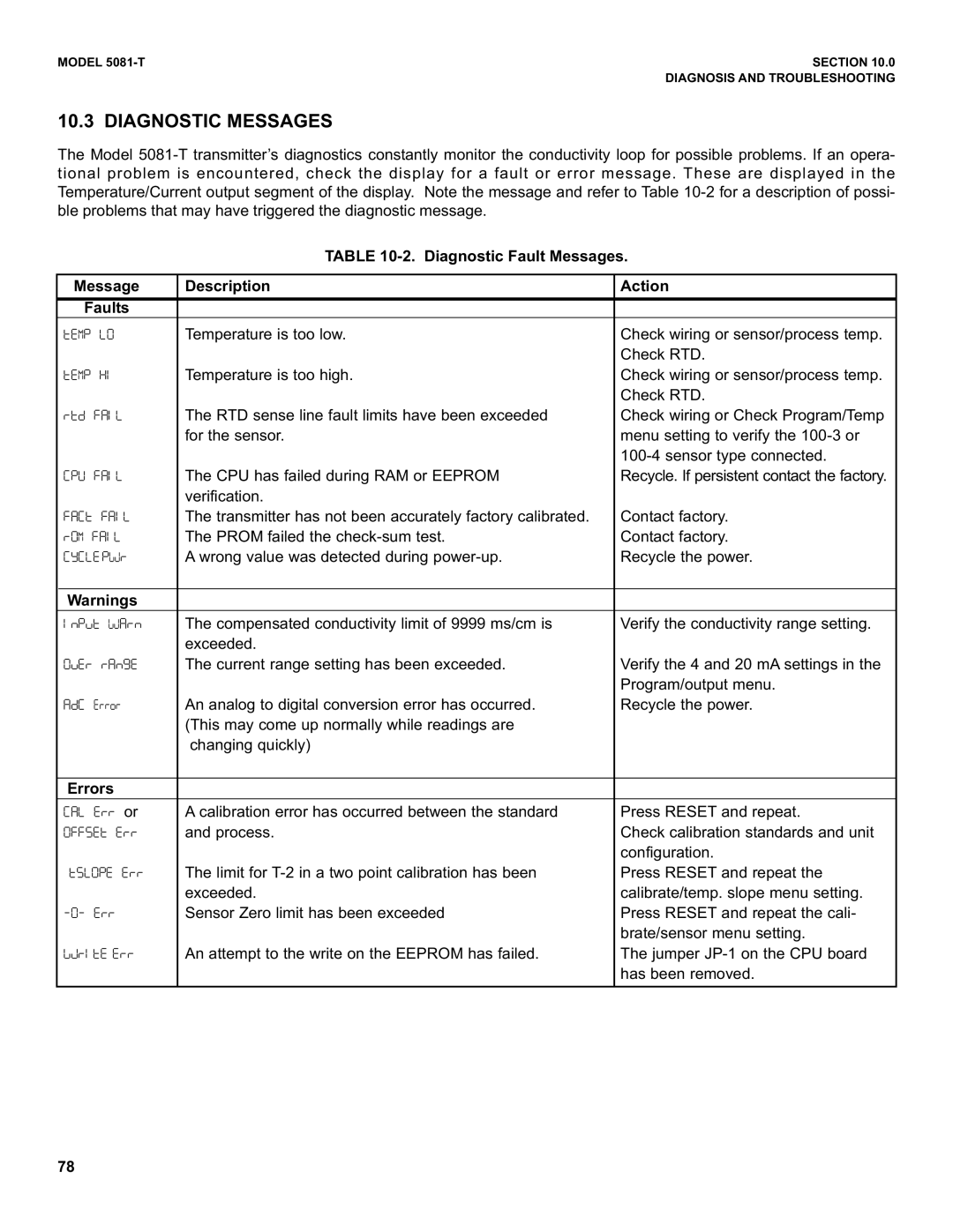
10.3 DIAGNOSTIC MESSAGES

The Model 5081-T transmitter’s diagnostics constantly monitor the conductivity loop for possible problems. If an opera- tional problem is encountered, check the display for a fault or error message. These are displayed in the Temperature/Current output segment of the display. Note the message and refer to Table 10-2 for a description of possi- ble problems that may have triggered the diagnostic message.

TABLE 10-2. Diagnostic Fault Messages.

Message

Description

Action


Faults


U17:![9

Temperature is too low.

Check wiring or sensor/process temp.


Check RTD.

U17:!45

Temperature is too high.

Check wiring or sensor/process temp.


Check RTD.

;UG!2-5[

The RTD sense line fault limits have been exceeded

Check wiring or Check Program/Temp


for the sensor.

menu setting to verify the 100-3 or


100-4 sensor type connected.

/:>!2-5[

The CPU has failed during RAM or EEPROM

Recycle. If persistent contact the factory.


verification.


2-/U!2-5[

The transmitter has not been accurately factory calibrated.

Contact factory.

S97 2-5[

The PROM failed the check-sum test.

Contact factory.

/A/[1 :@6S

A wrong value was detected during power-up.

Recycle the power.


Warnings


5P:VU!@6-SP

The compensated conductivity limit of 9999 ms/cm is

Verify the conductivity range setting.


exceeded.


9WHS!S-PJ1

The current range setting has been exceeded.

Verify the 4 and 20 mA settings in the


Program/output menu.

-G/!HSSQS

An analog to digital conversion error has occurred.

Recycle the power.


(This may come up normally while readings are


changing quickly)


Errors


/-[!1SS!or

A calibration error has occurred between the standard

Press RESET and repeat.

9IITHU!1SS

and process.

Check calibration standards and unit


configuration.

U<[9:1!1SS

The limit for T-2 in a two point calibration has been

Press RESET and repeat the


exceeded.

calibrate/temp. slope menu setting.

\"\!1SS

Sensor Zero limit has been exceeded

Press RESET and repeat the cali-


brate/sensor menu setting.

@M;5=1 1SS

An attempt to the write on the EEPROM has failed.

The jumper JP-1 on the CPU board


has been removed.


78

Page 84
Image 84
Emerson 5081-T instruction manual 9WHS!S-PJ1, Hssqs, 9IITHU!1SS