MODEL | SECTION 5.0 |
| DISPLAY AND OPERATION |
SECTION 5.0
DISPLAY AND OPERATION
5.1Displays
5.2Infrared Remote Controller (IRC) - Key Functions
5.3Quick Start for Model
5.4Quick Start for Model
5.5Menu Trees
5.6Diagnostic Messages
5.7Default Settings
5.8Security
5.9Using Hold
5.1 DISPLAYS
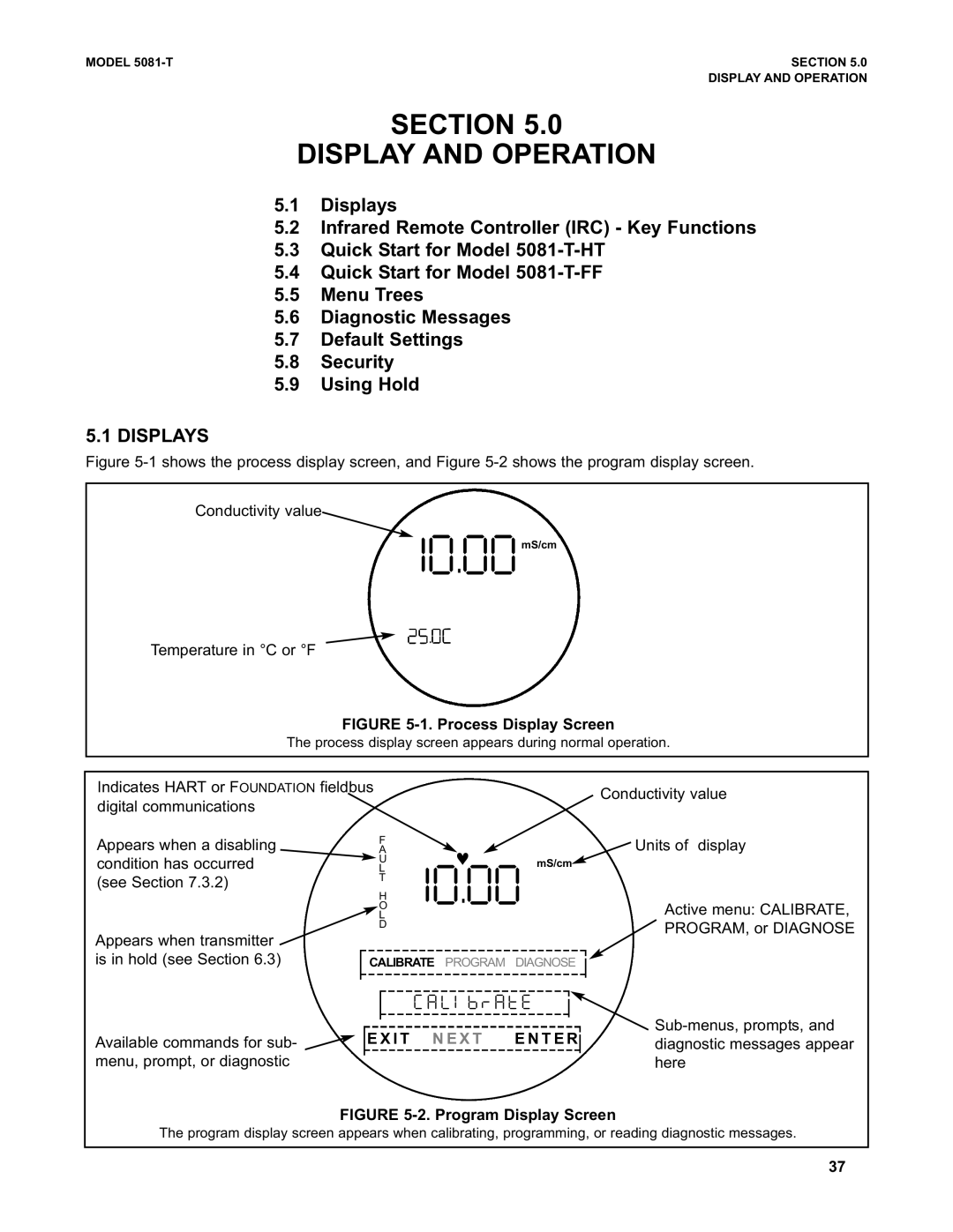
Figure 5-1 shows the process display screen, and Figure 5-2 shows the program display screen.
Conductivity value
#"c""mS/cm
Temperature in °C or °F
FIGURE 5-1. Process Display Screen
The process display screen appears during normal operation.
Indicates HART or FOUNDATION fieldbus |
|
|
|
|
| Conductivity value | |
digital communications |
|
|
|
|
|
| |
|
|
|
|
|
|
| |
Appears when a disabling | F | ♥ |
|
|
|
| Units of display |
A |
|
|
|
| |||
condition has occurred | U |
| mS/cm |
|
| ||
L | #"c"" |
|
| ||||
| H |
|
|
|
| ||
(see Section 7.3.2) | T |
|
|
|
|
|
|
|
|
|
|
|
|
| |
| O |
|
|
|
|
| Active menu: CALIBRATE, |
| L |
|
|
|
|
| |
| D |
|
|
|
|
| PROGRAM, or DIAGNOSE |
Appears when transmitter |
|
|
|
|
|
| |
|
|
|
|
|
|
| |
is in hold (see Section 6.3) | CALIBRATE PROGRAM | DIAGNOSE |
|
| |||
|
| ||||||
|
| / - [ 5 E S - U 1 |
|
|
| ||
|
|
|
|
| |||
|
|
|
|
| |||
|
|
|
|
|
|
| |
| E X I T N E X T | E N T E R |
| ||||
Available commands for sub- |
| diagnostic messages appear | |||||
| |||||||
|
|
|
|
|
| ||
menu, prompt, or diagnostic |
|
|
|
|
|
| here |
|
|
|
|
|
|
|
|
FIGURE 5-2. Program Display Screen
The program display screen appears when calibrating, programming, or reading diagnostic messages.
37