MODEL 5081-T | SECTION 3.0 |
| WIRING |
SECTION 3.0
WIRING
3.1Sensor Wiring
3.2Electrical Installation
3.1 SENSOR WIRING
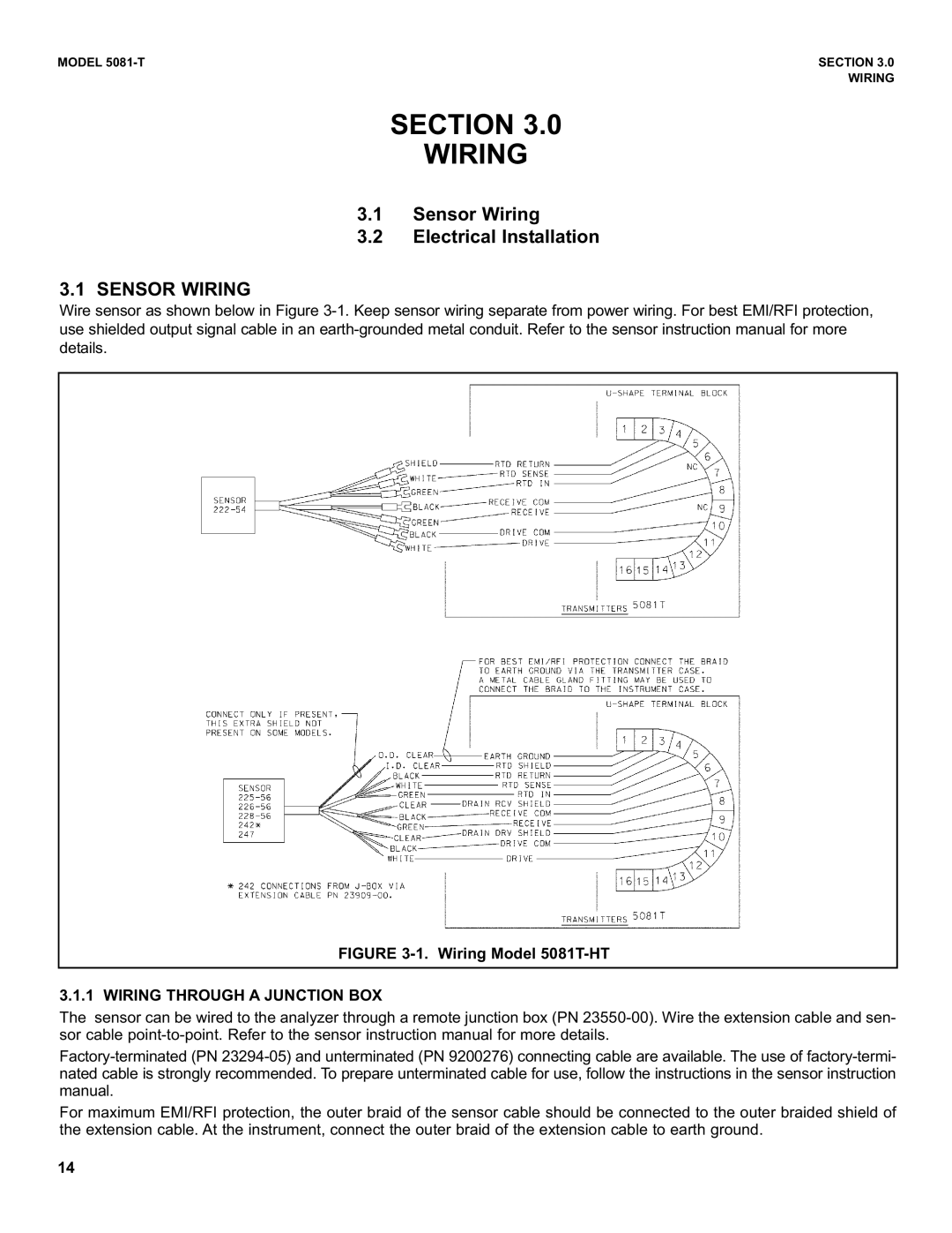
Wire sensor as shown below in Figure 3-1. Keep sensor wiring separate from power wiring. For best EMI/RFI protection, use shielded output signal cable in an earth-grounded metal conduit. Refer to the sensor instruction manual for more details.
FIGURE 3-1. Wiring Model 5081T-HT
3.1.1 WIRING THROUGH A JUNCTION BOX
The sensor can be wired to the analyzer through a remote junction box (PN 23550-00). Wire the extension cable and sen- sor cable point-to-point. Refer to the sensor instruction manual for more details.
Factory-terminated (PN 23294-05) and unterminated (PN 9200276) connecting cable are available. The use of factory-termi- nated cable is strongly recommended. To prepare unterminated cable for use, follow the instructions in the sensor instruction manual.
For maximum EMI/RFI protection, the outer braid of the sensor cable should be connected to the outer braided shield of the extension cable. At the instrument, connect the outer braid of the extension cable to earth ground.