MODEL | SECTION 5.0 |
| DISPLAY AND OPERATION |
5.6 DIAGNOSTIC MESSAGES
Whenever a warning or fault limit has been exceeded, the transmitter displays diagnostic messages to aid in trou- bleshooting. Diagnostic messages appear in the same area as the temperature/output readings in the process display screen (see Figure
See Section 10.0, Troubleshooting, for the meanings of the fault and warning messages.
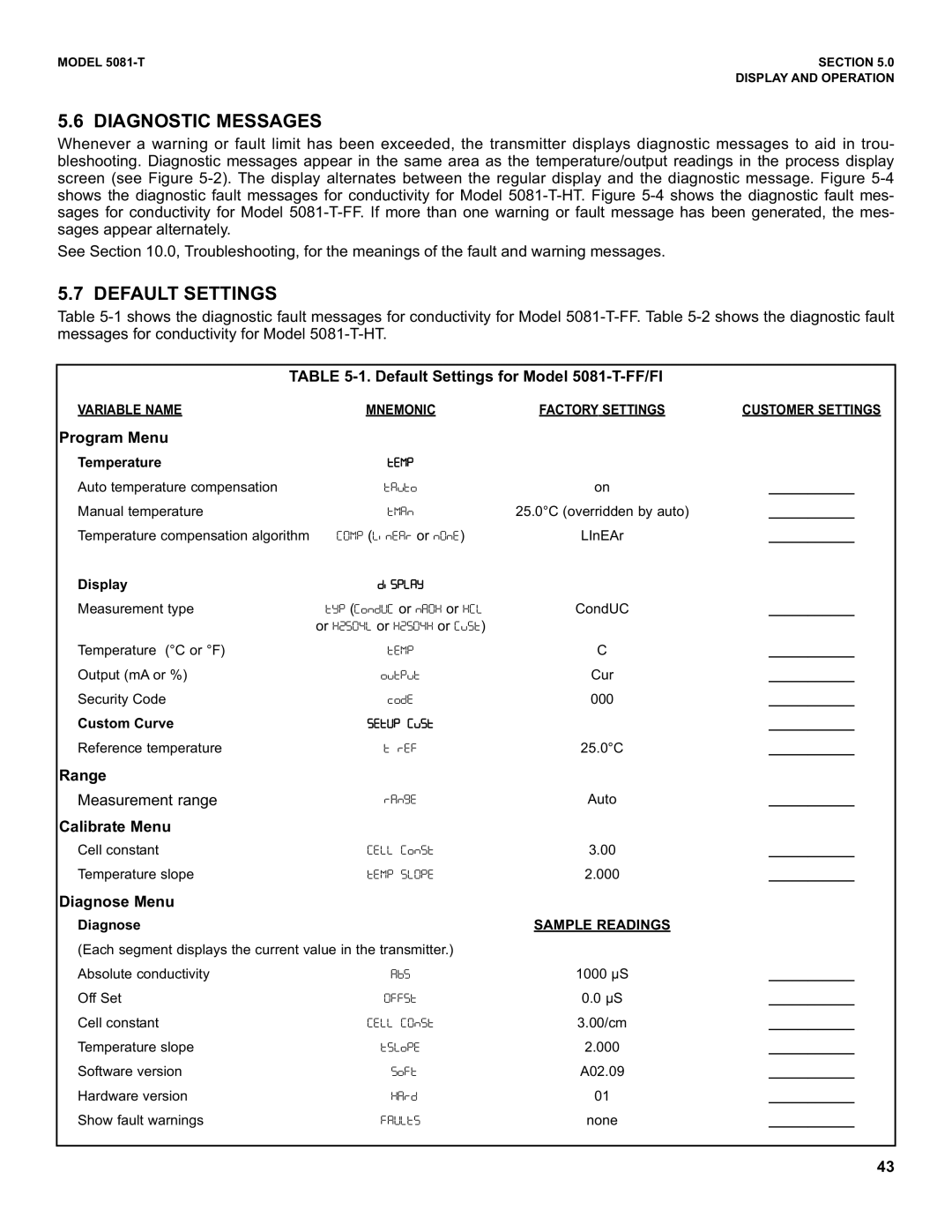
5.7 DEFAULT SETTINGS
Table
TABLE
VARIABLE NAMEMNEMONICFACTORY SETTINGS CUSTOMER SETTINGS
Program Menu
Temperature | UHOR |
|
|
Auto temperature compensation | UDVUQ | on | ___________ |
Manual temperature | UODP | 25.0°C (overridden by auto) | ___________ |
Temperature compensation algorithm | /97: ([LPHDS or P9P1) | LInEAr | ___________ |
Display | GLTRNDY |
|
|
Measurement type | UYR (/QPG>/ or | CondUC | ___________ |
| or 4$<9&[ or 4$<9&4 or /VTU) |
|
|
Temperature (°C or °F) | UHOR | C | ___________ |
Output (mA or %) | QVURVU | Cur | ___________ |
Security Code | FQGH | 000 | ___________ |
Custom Curve | <1U>:!/V<U |
| ___________ |
Reference temperature | U!SHI | 25.0°C | ___________ |
Range |
|
|
|
Measurement range | Auto | ___________ | |
Calibrate Menu |
|
|
|
Cell constant | /1[[!/QPTU | 3.00 | ___________ |
Temperature slope | U17:!TN9RH | 2.000 | ___________ |
Diagnose Menu |
|
|
|
Diagnose |
| SAMPLE READINGS |
|
(Each segment displays the current value in the transmitter.) |
|
| |
Absolute conductivity | 1000 µS | ___________ | |
Off Set | 9II<U | 0.0 µS | ___________ |
Cell constant | /1[[!/9P<U | 3.00/cm | ___________ |
Temperature slope | UTNQRH | 2.000 | ___________ |
Software version | TQIU | A02.09 | ___________ |
Hardware version | 01 | ___________ | |
Show fault warnings | 2D>[=< | none | ___________ |
43