MODEL
2.5POWER SUPPLY WIRING FOR MODEL 5081-T-FF/FI
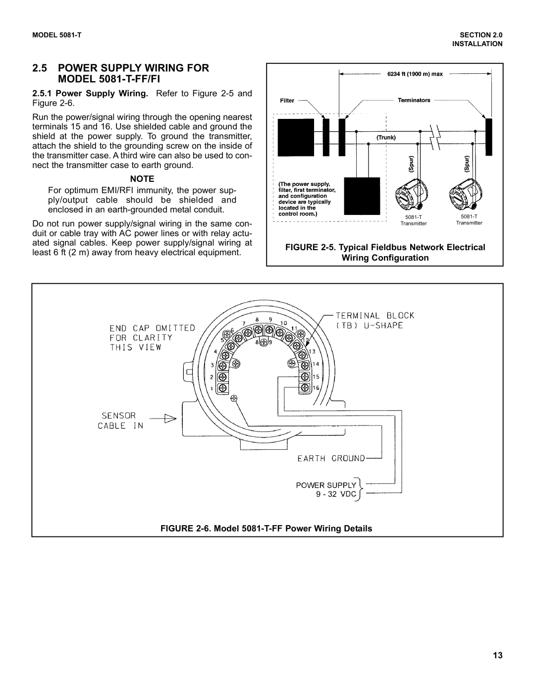
2.5.1Power Supply Wiring. Refer to Figure
Run the power/signal wiring through the opening nearest terminals 15 and 16. Use shielded cable and ground the shield at the power supply. To ground the transmitter, attach the shield to the grounding screw on the inside of the transmitter case. A third wire can also be used to con- nect the transmitter case to earth ground.
NOTE
For optimum EMI/RFI immunity, the power sup- ply/output cable should be shielded and enclosed in an
Do not run power supply/signal wiring in the same con- duit or cable tray with AC power lines or with relay actu- ated signal cables. Keep power supply/signal wiring at least 6 ft (2 m) away from heavy electrical equipment.
SECTION 2.0
INSTALLATION
Transmitter Transmitter
FIGURE 2-5. Typical Fieldbus Network Electrical
Wiring Configuration
9 - 32
FIGURE 2-6. Model 5081-T-FF Power Wiring Details
13