MODEL
1.4TRANSMITTER DISPLAY DURING CALIBRATION AND PROGRAMMING (FIGURE
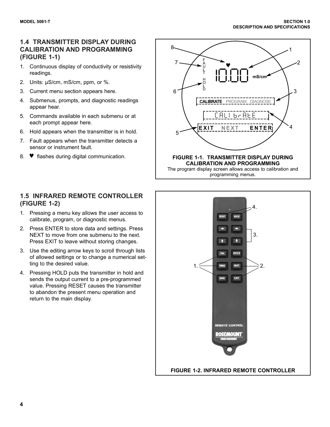
1.Continuous display of conductivity or resistivity readings.
2.Units: µS/cm, mS/cm, ppm, or %.
3.Current menu section appears here.
4.Submenus, prompts, and diagnostic readings appear hear.
5.Commands available in each submenu or at each prompt appear here.
6.Hold appears when the transmitter is in hold.
7.Fault appears when the transmitter detects a sensor or instrument fault.
8.♥ flashes during digital communication.
1.5INFRARED REMOTE CONTROLLER (FIGURE 1-2)
1.Pressing a menu key allows the user access to calibrate, program, or diagnostic menus.
2.Press ENTER to store data and settings. Press NEXT to move from one submenu to the next. Press EXIT to leave without storing changes.
3.Use the editing arrow keys to scroll through lists of allowed settings or to change a numerical set- ting to the desired value.
4.Pressing HOLD puts the transmitter in hold and sends the output current to a
|
|
|
|
|
|
|
|
| SECTION 1.0 |
|
|
| DESCRIPTION AND SPECIFICATIONS | ||||||
|
|
|
|
|
|
|
|
|
|
8 |
|
|
|
|
|
| 1 | ||
|
|
|
|
|
|
| |||
7 | F | ♥ |
|
|
| 2 | |||
A |
|
|
| ||||||
|
| U |
|
|
|
|
|
|
|
|
| L | #"c"" mS/cm |
|
|
| |||
|
| H |
|
|
| ||||
|
| T |
|
|
|
|
|
|
|
|
| O |
|
|
|
|
|
|
|
|
| L |
|
|
|
|
|
|
|
6 | D |
|
|
|
| 3 | |||
|
|
|
|
| |||||
|
| CALIBRATE PROGRAM | DIAGNOSE |
|
|
| |||
|
|
|
|
| |||||
|
|
| / - [ 5 E S - U 1 |
|
|
| 4 | ||
|
|
|
|
| |||||
|
|
|
|
|
|
| |||
|
| E X I T N E X T | E N T E R |
| |||||
|
|
| |||||||
| 5 |
|
|
|
|
|
|
|
|
|
|
|
|
|
|
|
| ||
|
|
|
|
|
|
|
|
|
|
FIGURE 1-1. TRANSMITTER DISPLAY DURING
CALIBRATION AND PROGRAMMING
The program display screen allows access to calibration and
programming menus.
4.
3.
1.2.
FIGURE 1-2. INFRARED REMOTE CONTROLLER
4