MODEL | SECTION 11.0 |
| MAINTENANCE |
SECTION 11.0
MAINTENANCE
11.1 OVERVIEW
Maintenance consists of "Preventative" and "Corrective" measures.
11.2 PREVENTATIVE MAINTENANCE
11.2.1Transmitter Maintenance. Transmitter mainte- nance consists of periodic calibration. A monthly cali- bration is a good starting maintenance schedule. This schedule can then be fine tuned to the site process.
11.2.2Sensor Maintenance. Sensor maintenance consists of periodic cleaning of the electrode.
A weekly cleaning is a good starting maintenance schedule. This schedule can then be fine tuned to the site process.
11.2.3Initiating HOLD Function For Maintenance. To place the transmitter into the Hold operational mode prior to servicing the sensor, press the HOLD key on the IRC (infrared remote control). The mes- sage field will respond with a message concerning the present hold condition. Press the IRC editing key to toggle to the On condition. Press ENTER to activate HOLD output.
Hold Mode will maintain the operating current output at the programmed value regardless of process changes. Refer to Section 7.2.3, step 4, for instruc- tions on how to set this value.
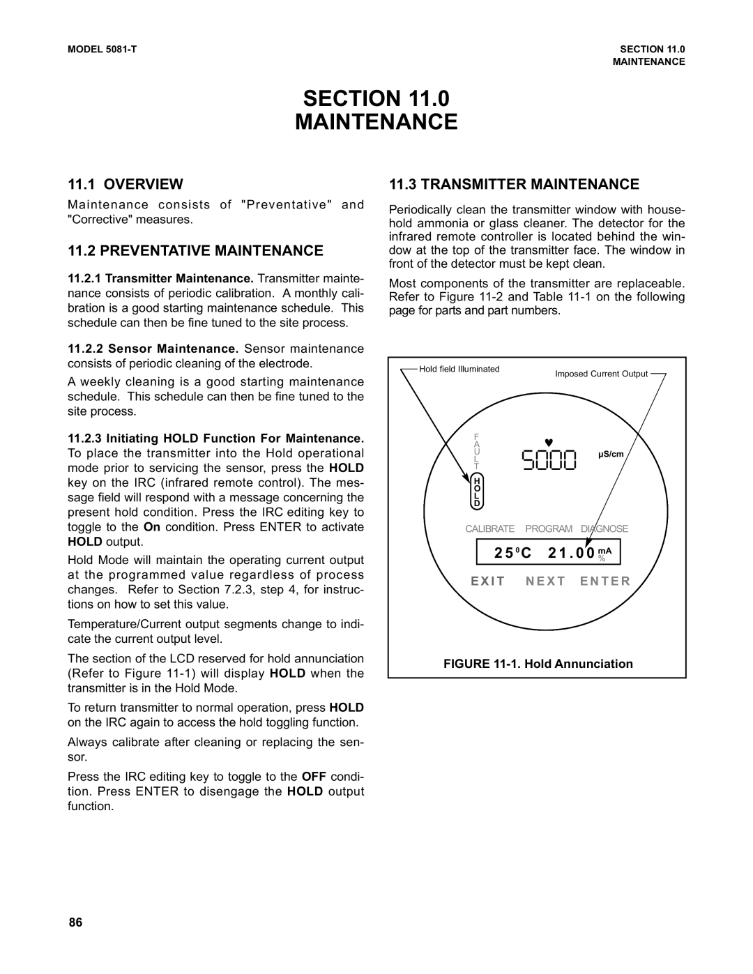
Temperature/Current output segments change to indi- cate the current output level.
The section of the LCD reserved for hold annunciation (Refer to Figure
To return transmitter to normal operation, press HOLD on the IRC again to access the hold toggling function.
Always calibrate after cleaning or replacing the sen- sor.
Press the IRC editing key to toggle to the OFF condi- tion. Press ENTER to disengage the HOLD output function.
11.3 TRANSMITTER MAINTENANCE
Periodically clean the transmitter window with house- hold ammonia or glass cleaner. The detector for the infrared remote controller is located behind the win- dow at the top of the transmitter face. The window in front of the detector must be kept clean.
Most components of the transmitter are replaceable. Refer to Figure
Hold field Illuminated | Imposed Current Output | ||
| |||
F | ♥ |
| |
A |
| ||
U | '""" | µS/cm | |
L | |||
| |||
T |
| ||
H |
|
| |
O |
|
| |
L |
|
| |
D |
|
| |
CALIBRATE | PROGRAM | DIAGNOSE | |
2 5 0 C 2 1 . 0 0 %mA | |||
E X I T N E X T E N T E R | |||
FIGURE | |||
86