MODEL | SECTION 1.0 |
| DESCRIPTION AND SPECIFICATIONS |
1.2 SPECIFICATIONS
1.2.1 GENERAL SPECIFICATIONS
Enclosure: Cast aluminum containing less than 6% mag- nesium, with epoxy polyester coating. NEMA 4X (IP65) and NEMA 7B. Neoprene
Dimensions: See drawing.
Conduit Openings: ¾-in. FNPT
Ambient Temperature:
Storage Temperature:
Relative Humidity: 0 to 95%
Weight/Shipping Weight: 10 lb/10 lb (4.5/5.0 kg)
Display:
First line: 7 segment LCD, 0.8 in. (20 mm) high.
Second line: 7 segment LCD, 0.3 in. (7mm) high.
Display board can be rotated 90 degrees clockwise or counterclockwise.
During calibration and programming, messages and prompts appear in the second line.
Temperature resolution: 0.1°C
Hazardous Location Approval: For details, see specifi- cations for the measurement of interest.
RFI/EMI:
Digital Communications:
HART —
Power & Load Requirements:
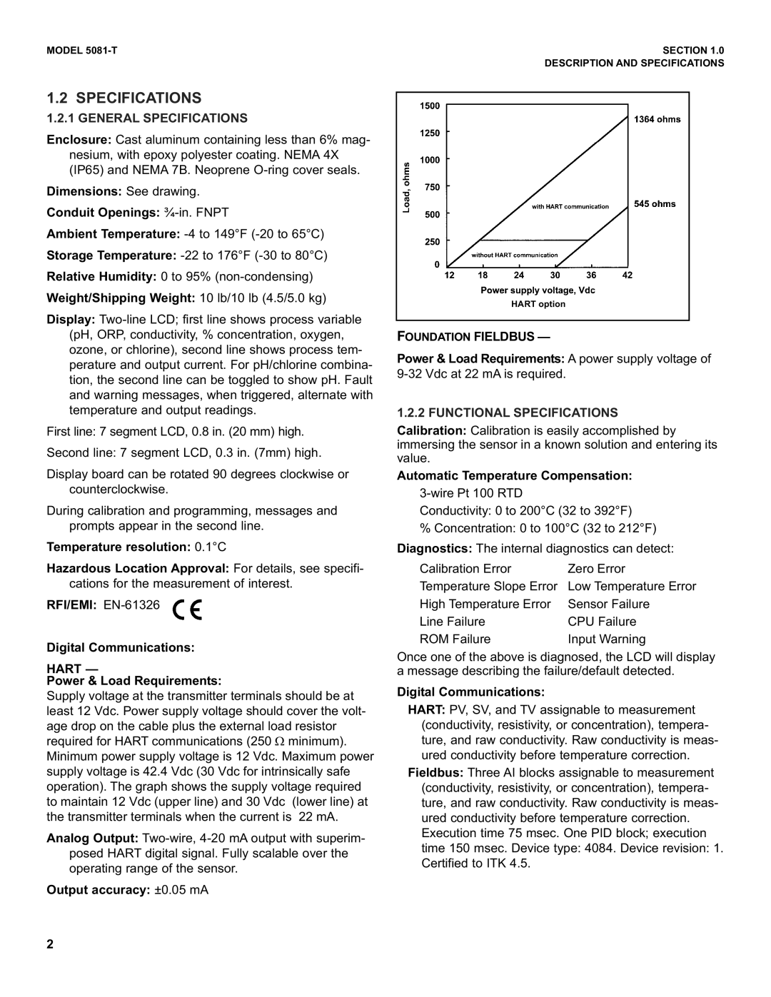
Supply voltage at the transmitter terminals should be at least 12 Vdc. Power supply voltage should cover the volt- age drop on the cable plus the external load resistor required for HART communications (250 Ω minimum). Minimum power supply voltage is 12 Vdc. Maximum power supply voltage is 42.4 Vdc (30 Vdc for intrinsically safe operation). The graph shows the supply voltage required to maintain 12 Vdc (upper line) and 30 Vdc (lower line) at the transmitter terminals when the current is 22 mA.
Analog Output:
Output accuracy: ±0.05 mA
HART option
FOUNDATION FIELDBUS —
Power & Load Requirements: A power supply voltage of
1.2.2 FUNCTIONAL SPECIFICATIONS
Calibration: Calibration is easily accomplished by immersing the sensor in a known solution and entering its value.
Automatic Temperature Compensation:
Conductivity: 0 to 200°C (32 to 392°F)
% Concentration: 0 to 100°C (32 to 212°F)
Diagnostics: The internal diagnostics can detect:
Calibration Error | Zero Error |
Temperature Slope Error | Low Temperature Error |
High Temperature Error | Sensor Failure |
Line Failure | CPU Failure |
ROM Failure | Input Warning |
Once one of the above is diagnosed, the LCD will display a message describing the failure/default detected.
Digital Communications:
HART: PV, SV, and TV assignable to measurement (conductivity, resistivity, or concentration), tempera- ture, and raw conductivity. Raw conductivity is meas- ured conductivity before temperature correction.
Fieldbus: Three AI blocks assignable to measurement (conductivity, resistivity, or concentration), tempera- ture, and raw conductivity. Raw conductivity is meas- ured conductivity before temperature correction. Execution time 75 msec. One PID block; execution time 150 msec. Device type: 4084. Device revision: 1. Certified to ITK 4.5.
2