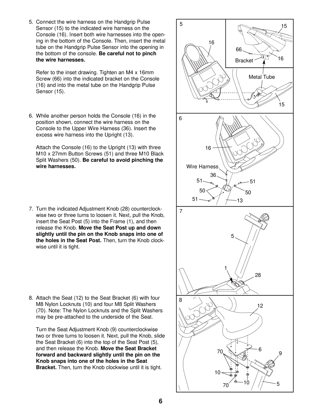
5.Connect the wire harness on the Handgrip Pulse Sensor (15) to the indicated wire harness on the Console (16). Insert both wire harnesses into the open- ing in the bottom of the Console. Then, insert the metal tube on the Handgrip Pulse Sensor into the opening in the bottom of the console. Be careful not to pinch the wire harnesses.
Refer to the inset drawing. Tighten an M4 x 16mm Screw (66) into the indicated bracket on the Console (16) and into the metal tube on the Handgrip Pulse Sensor (15).
6.While another person holds the Console (16) in the position shown, connect the wire harness on the Console to the Upper Wire Harness (36). Insert the excess wire harness into the Upright (13).
Attach the Console (16) to the Upright (13) with three M10 x 27mm Button Screws (51) and three M10 Black Split Washers (50). Be careful to avoid pinching the wire harnesses.
7.Turn the indicated Adjustment Knob (28) counterclock- wise two or three turns to loosen it. Next, pull the Knob, insert the Seat Post (5) into the Frame (1), and then release the Knob. Move the Seat Post up and down slightly until the pin on the Knob snaps into one of the holes in the Seat Post. Then, turn the Knob clock- wise until it is tight.
8.Attach the Seat (12) to the Seat Bracket (6) with four M8 Nylon Locknuts (10) and four M8 Split Washers (70). Note: The Nylon Locknuts and the Split Washers may be
Turn the Seat Adjustment Knob (9) counterclockwise two or three turns to loosen it. Next, pull the Knob, slide the Seat Bracket (6) into the top of the Seat Post (5), and then release the Knob. Move the Seat Bracket forward and backward slightly until the pin on the Knob snaps into one of the holes in the Seat Bracket. Then, turn the Knob clockwise until it is tight.
6
5 |
| 15 |
|
| |
16 |
|
|
| 66 |
|
| Bracket | 16 |
|
| |
| Metal Tube |
|
|
| 15 |
6 |
|
|
16 |
|
|
Wire Harness |
|
|
36 |
|
|
51 | 51 |
|
50 | 50 |
|
|
| |
51 | 13 |
|
7 |
|
|
| 5 |
|
1 |
|
|
| 28 |
|
8 | 12 |
|
|
| |
70 | 6 | 9 |
| ||
|
| |
10 |
|
|
70 | 10 | 5 |
