Air is introduced to the duct smoke detector sensor’s sensing chamber through a sampling tube that extends into the HVAC duct and is directed back into the ventilation system through a (shorter) exhaust tube. The difference in air pressure between the two tubes pulls the sampled air through the sensing chamber. When a sufficient amount of smoke is detected in the sensing chamber, the sensor signals an alarm state and the controller automatically takes the appropriate action to shut down fans and blowers, change over air handling systems, notify the fire alarm control panel, etc.

The sensor uses a process called differential sensing to prevent gradual environmental changes from triggering false alarms. A rapid change in environmental conditions, such as smoke from a fire, causes the sensor to signal an alarm state but dust and debris accumulated over time does not.

For installations using two sensors, the duct smoke detector does not differentiate which sensor signals an alarm or trouble condition.

Smoke Detector Locations

Supply Air —

The Supply Air smoke detector sensor is located to the left of the unit’s indoor (supply) fan. See Fig. 83. Access is through the left side blower access panel. There is no sampling tube used at this location. The sampling tube inlet extends through the side plate of the fan housing (into a high pressure area). The controller is located on a bracket to the right of the return filter, accessed through the lift-off filter panel.

Smoke Detector Sensor

C08245

Fig. 83 - Typical Supply Air Smoke Detector Sensor

Location

Return Air without Economizer —


The sampling tube is located across the return air opening


on the unit basepan. See Fig. 86. The holes in the


sampling tube face downward, into the return air stream.


The sampling tube is connected via tubing to the return air


sensor that is mounted on a bracket high on the partition


between return filter and controller location. (This sensor


is shipped in a flat-mounting location. Installation


requires that this sensor be relocated to its operating


location and the tubing to the sampling tube be connected.


See “Completing Installation of Return Air Smoke


Sensor:” for details.)


Return Air with Economizer —


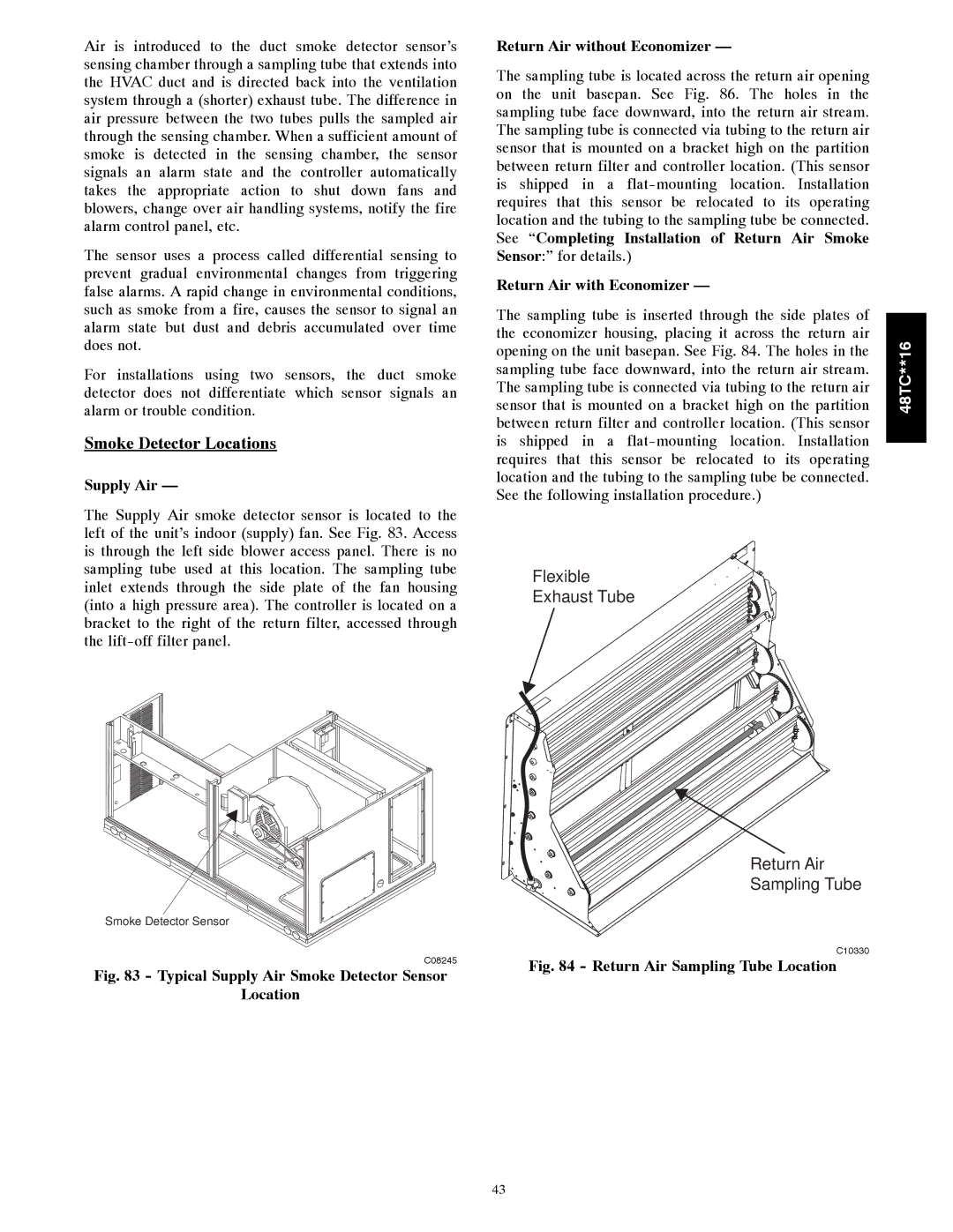
The sampling tube is inserted through the side plates of


the economizer housing, placing it across the return air

48TC**16

opening on the unit basepan. See Fig. 84. The holes in the

sensor that is mounted on a bracket high on the partition

sampling tube face downward, into the return air stream.


The sampling tube is connected via tubing to the return air


between return filter and controller location. (This sensor


is shipped in a flat-mounting location. Installation


requires that this sensor be relocated to its operating


location and the tubing to the sampling tube be connected.


See the following installation procedure.)


Flexible

Exhaust Tube

Return Air

Sampling Tube

C10330

Fig. 84 - Return Air Sampling Tube Location

43

Page 43
Image 43
Carrier 48TC**16 Smoke Detector Locations, Supply Air, See Completing Installation of Return Air Smoke

48TC**16 specifications

The Carrier 48TC**16 is a high-efficiency rooftop packaged unit, designed for commercial heating and cooling applications. This model exemplifies Carrier's commitment to delivering reliable and innovative solutions to the HVAC industry. With cutting-edge technology and robust performance characteristics, the 48TC**16 is ideally suited for a variety of building types.

One of the main features of the Carrier 48TC**16 is its impressive energy efficiency. The unit achieves high SEER (Seasonal Energy Efficiency Ratio) ratings, which translates to lower energy bills and reduced environmental impact. The unit is equipped with a scroll compressor, known for its quiet operation and reliability, ensuring a comfortable indoor environment without disruptive noise.

The 48TC**16 utilizes advanced microprocessor controls that enhance system performance by enabling precise temperature control and various operational modes. This allows users to optimize the system's performance based on specific heating and cooling needs. Additionally, the unit includes enhanced diagnostics, allowing for faster troubleshooting and easier maintenance, thus minimizing downtime and repair costs.

Another notable characteristic of the 48TC**16 is its robust construction. Built to withstand harsh weather conditions, the unit features a galvanized steel cabinet coated with a corrosion-resistant finish, ensuring longevity and durability. It also comes equipped with a variety of factory-installed options, such as economizers and filtration systems, which can further enhance its performance and flexibility.

The Carrier 48TC**16 is designed with sustainability in mind, using environmentally friendly refrigerants. The unit supports the latest refrigerant regulations, helping to reduce the overall carbon footprint of the building it serves.

Installation and service are simplified by the unit's modular design, which allows for easy access to all major components. This design not only streamlines maintenance procedures but also facilitates quick installation, making it an ideal choice for contractors and facility managers alike.

In summary, the Carrier 48TC**16 rooftop packaged unit combines high energy efficiency, advanced controls, robust construction, and eco-friendly features, making it a top choice for commercial heating and cooling needs. Its user-friendly design and reliability ensure optimal performance and comfort for various applications, underscoring Carrier's reputation as a leader in the HVAC industry. Whether for new construction or retrofitting, the 48TC**16 meets the demands of modern buildings while adhering to sustainability practices.