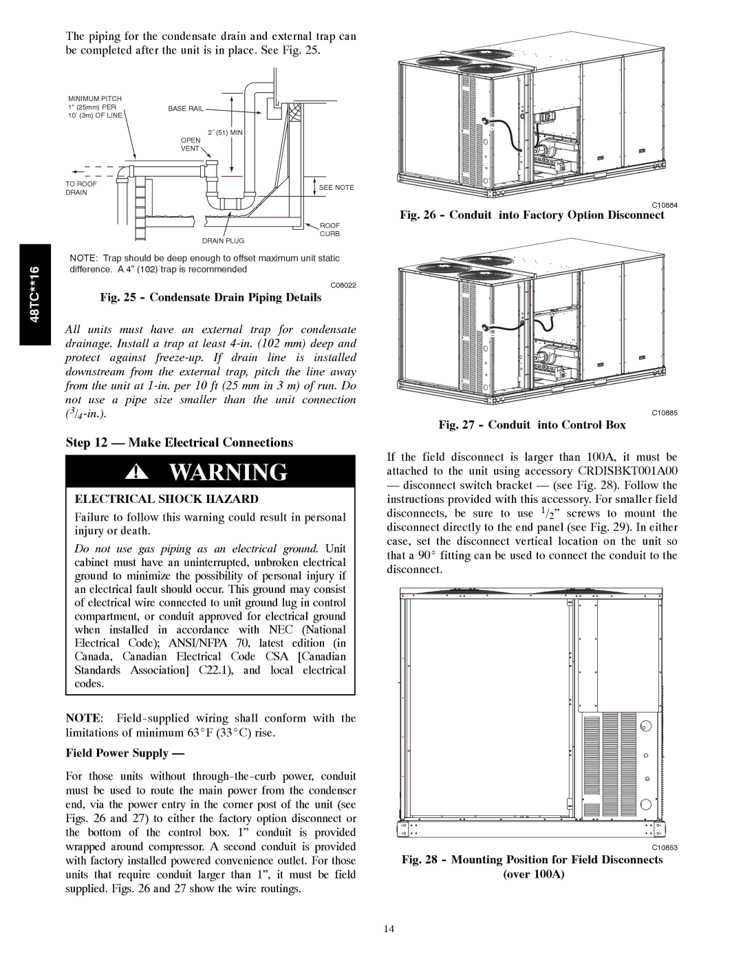
The piping for the condensate drain and external trap can be completed after the unit is in place. See Fig. 25.

MINIMUM PITCH

1” (25mm) PER

10’ (3m) OF LINE

TO ROOF

DRAIN

BASE RAIL

2˝ (51) MIN

OPEN

VENT

SEE NOTE

ROOF

CURB

DRAIN PLUG

C10884

Fig. 26 - Conduit into Factory Option Disconnect

48TC**16

NOTE: Trap should be deep enough to offset maximum unit static difference. A 4” (102) trap is recommended.

C08022

Fig. 25 - Condensate Drain Piping Details

All units must have an external trap for condensate drainage. Install a trap at least 4-in. (102 mm) deep and protect against freeze-up. If drain line is installed downstream from the external trap, pitch the line away from the unit at 1-in. per 10 ft (25 mm in 3 m) of run. Do not use a pipe size smaller than the unit connection (3/4-in.).

Step 12 — Make Electrical Connections

!WARNING

ELECTRICAL SHOCK HAZARD

Failure to follow this warning could result in personal injury or death.

Do not use gas piping as an electrical ground. Unit cabinet must have an uninterrupted, unbroken electrical ground to minimize the possibility of personal injury if an electrical fault should occur. This ground may consist of electrical wire connected to unit ground lug in control compartment, or conduit approved for electrical ground when installed in accordance with NEC (National Electrical Code); ANSI/NFPA 70, latest edition (in Canada, Canadian Electrical Code CSA [Canadian Standards Association] C22.1), and local electrical codes.

NOTE: Field-supplied wiring shall conform with the limitations of minimum 63_F (33_C) rise.

Field Power Supply —

For those units without through-the-curb power, conduit must be used to route the main power from the condenser end, via the power entry in the corner post of the unit (see Figs. 26 and 27) to either the factory option disconnect or the bottom of the control box. 1” conduit is provided wrapped around compressor. A second conduit is provided with factory installed powered convenience outlet. For those units that require conduit larger than 1”, it must be field supplied. Figs. 26 and 27 show the wire routings.

C10885

Fig. 27 - Conduit into Control Box

If the field disconnect is larger than 100A, it must be attached to the unit using accessory CRDISBKT001A00

disconnect switch bracket — (see Fig. 28). Follow the instructions provided with this accessory. For smaller field disconnects, be sure to use 1/2” screws to mount the disconnect directly to the end panel (see Fig. 29). In either case, set the disconnect vertical location on the unit so that a 90_ fitting can be used to connect the conduit to the disconnect.

C10853

Fig. 28 - Mounting Position for Field Disconnects

(over 100A)

14

Page 14
Image 14
Carrier 48TC**16 installation instructions Make Electrical Connections, Field Power Supply

48TC**16 specifications

The Carrier 48TC**16 is a high-efficiency rooftop packaged unit, designed for commercial heating and cooling applications. This model exemplifies Carrier's commitment to delivering reliable and innovative solutions to the HVAC industry. With cutting-edge technology and robust performance characteristics, the 48TC**16 is ideally suited for a variety of building types.

One of the main features of the Carrier 48TC**16 is its impressive energy efficiency. The unit achieves high SEER (Seasonal Energy Efficiency Ratio) ratings, which translates to lower energy bills and reduced environmental impact. The unit is equipped with a scroll compressor, known for its quiet operation and reliability, ensuring a comfortable indoor environment without disruptive noise.

The 48TC**16 utilizes advanced microprocessor controls that enhance system performance by enabling precise temperature control and various operational modes. This allows users to optimize the system's performance based on specific heating and cooling needs. Additionally, the unit includes enhanced diagnostics, allowing for faster troubleshooting and easier maintenance, thus minimizing downtime and repair costs.

Another notable characteristic of the 48TC**16 is its robust construction. Built to withstand harsh weather conditions, the unit features a galvanized steel cabinet coated with a corrosion-resistant finish, ensuring longevity and durability. It also comes equipped with a variety of factory-installed options, such as economizers and filtration systems, which can further enhance its performance and flexibility.

The Carrier 48TC**16 is designed with sustainability in mind, using environmentally friendly refrigerants. The unit supports the latest refrigerant regulations, helping to reduce the overall carbon footprint of the building it serves.

Installation and service are simplified by the unit's modular design, which allows for easy access to all major components. This design not only streamlines maintenance procedures but also facilitates quick installation, making it an ideal choice for contractors and facility managers alike.

In summary, the Carrier 48TC**16 rooftop packaged unit combines high energy efficiency, advanced controls, robust construction, and eco-friendly features, making it a top choice for commercial heating and cooling needs. Its user-friendly design and reliability ensure optimal performance and comfort for various applications, underscoring Carrier's reputation as a leader in the HVAC industry. Whether for new construction or retrofitting, the 48TC**16 meets the demands of modern buildings while adhering to sustainability practices.