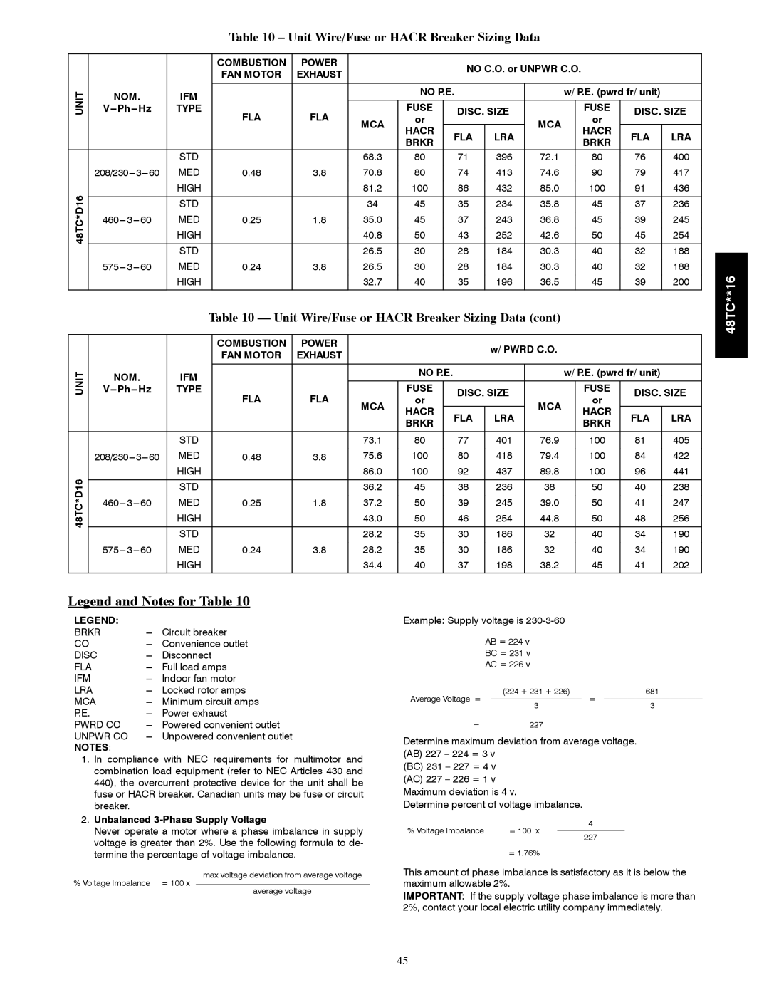
Table 10 – Unit Wire/Fuse or HACR Breaker Sizing Data


COMBUSTION

POWER


NO C.O. or UNPWR C.O.


FAN MOTOR

EXHAUST


UNIT

NOM.

IFM


NO P.E.


w/ P.E. (pwrd fr/ unit)


V---Ph---Hz

TYPE

FLA

FLA


FUSE

DISC. SIZE


FUSE

DISC. SIZE


MCA

or


MCA


or


HACR

FLA

LRA


HACR

FLA

LRA


BRKR


BRKR


STD


68.3

80

71

396

72.1


80

76

400


208/230---3---60

MED

0.48

3.8

70.8

80

74

413

74.6


90

79

417

48TC*D16


HIGH


81.2

100

86

432

85.0


100

91

436


STD


34

45

35

234

35.8


45

37

236


460--- 3--- 60

MED

0.25

1.8

35.0

45

37

243

36.8


45

39

245


HIGH


40.8

50

43

252

42.6


50

45

254


STD


26.5

30

28

184

30.3


40

32

188


575--- 3--- 60

MED

0.24

3.8

26.5

30

28

184

30.3


40

32

188


HIGH


32.7

40

35

196

36.5


45

39

200


Table 10 — Unit Wire/Fuse or HACR Breaker Sizing Data (cont)


COMBUSTION

POWER


w/ PWRD C.O.


FAN MOTOR

EXHAUST


UNIT

NOM.

IFM


NO P.E.


w/ P.E. (pwrd fr/ unit)


V---Ph---Hz

TYPE

FLA

FLA


FUSE


DISC. SIZE


FUSE

DISC. SIZE


or


or


MCA


MCA


HACR


FLA

LRA


HACR

FLA

LRA


BRKR


BRKR


STD


73.1

80


77

401

76.9


100

81

405


208/230---3---60

MED

0.48

3.8

75.6

100


80

418

79.4


100

84

422

48TC*D16


HIGH


86.0

100


92

437

89.8


100

96

441


STD


36.2

45


38

236

38


50

40

238

460--- 3--- 60

MED

0.25

1.8

37.2

50


39

245

39.0


50

41

247


HIGH


43.0

50


46

254

44.8


50

48

256


STD


28.2

35


30

186

32


40

34

190


575--- 3--- 60

MED

0.24

3.8

28.2

35


30

186

32


40

34

190


HIGH


34.4

40


37

198

38.2


45

41

202


48TC**16

Legend and Notes for Table 10

LEGEND:


BRKR

---

Circuit breaker

CO

---

Convenience outlet

DISC

---

Disconnect

FLA

---

Full load amps

IFM

---

Indoor fan motor

LRA

---

Locked rotor amps

MCA

---

Minimum circuit amps

P.E.

---

Power exhaust

PWRD CO

---

Powered convenient outlet

UNPWR CO

---

Unpowered convenient outlet

NOTES:


1.In compliance with NEC requirements for multimotor and combination load equipment (refer to NEC Articles 430 and 440), the overcurrent protective device for the unit shall be fuse or HACR breaker. Canadian units may be fuse or circuit breaker.

2.Unbalanced 3-Phase Supply Voltage

Never operate a motor where a phase imbalance in supply voltage is greater than 2%. Use the following formula to de- termine the percentage of voltage imbalance.

max voltage deviation from average voltage

% Voltage Imbalance = 100 x

average voltage

Example: Supply voltage is 230-3-60

AB = 224 v

BC = 231 v

AC = 226 v

Average Voltage =

(224 + 231 + 226)

=

681


3

3


=227

Determine maximum deviation from average voltage. (AB) 227 – 224 = 3 v

(BC) 231 – 227 = 4 v (AC) 227 – 226 = 1 v Maximum deviation is 4 v.

Determine percent of voltage imbalance.

% Voltage Imbalance

= 100 x

4


227


= 1.76%


This amount of phase imbalance is satisfactory as it is below the maximum allowable 2%.

IMPORTANT: If the supply voltage phase imbalance is more than 2%, contact your local electric utility company immediately.

45

Page 45
Image 45
Carrier 48TC**16 installation instructions Unit Wire/Fuse or Hacr Breaker Sizing Data, Brkr

48TC**16 specifications

The Carrier 48TC**16 is a high-efficiency rooftop packaged unit, designed for commercial heating and cooling applications. This model exemplifies Carrier's commitment to delivering reliable and innovative solutions to the HVAC industry. With cutting-edge technology and robust performance characteristics, the 48TC**16 is ideally suited for a variety of building types.

One of the main features of the Carrier 48TC**16 is its impressive energy efficiency. The unit achieves high SEER (Seasonal Energy Efficiency Ratio) ratings, which translates to lower energy bills and reduced environmental impact. The unit is equipped with a scroll compressor, known for its quiet operation and reliability, ensuring a comfortable indoor environment without disruptive noise.

The 48TC**16 utilizes advanced microprocessor controls that enhance system performance by enabling precise temperature control and various operational modes. This allows users to optimize the system's performance based on specific heating and cooling needs. Additionally, the unit includes enhanced diagnostics, allowing for faster troubleshooting and easier maintenance, thus minimizing downtime and repair costs.

Another notable characteristic of the 48TC**16 is its robust construction. Built to withstand harsh weather conditions, the unit features a galvanized steel cabinet coated with a corrosion-resistant finish, ensuring longevity and durability. It also comes equipped with a variety of factory-installed options, such as economizers and filtration systems, which can further enhance its performance and flexibility.

The Carrier 48TC**16 is designed with sustainability in mind, using environmentally friendly refrigerants. The unit supports the latest refrigerant regulations, helping to reduce the overall carbon footprint of the building it serves.

Installation and service are simplified by the unit's modular design, which allows for easy access to all major components. This design not only streamlines maintenance procedures but also facilitates quick installation, making it an ideal choice for contractors and facility managers alike.

In summary, the Carrier 48TC**16 rooftop packaged unit combines high energy efficiency, advanced controls, robust construction, and eco-friendly features, making it a top choice for commercial heating and cooling needs. Its user-friendly design and reliability ensure optimal performance and comfort for various applications, underscoring Carrier's reputation as a leader in the HVAC industry. Whether for new construction or retrofitting, the 48TC**16 meets the demands of modern buildings while adhering to sustainability practices.