C


A


MAXIMUM ALLOWABLE


DIFFERENCE IN. (MM)


B


A-B

B-C

A-C


0.5” (13)

1.0” (25)

1.0” (25)

C10001

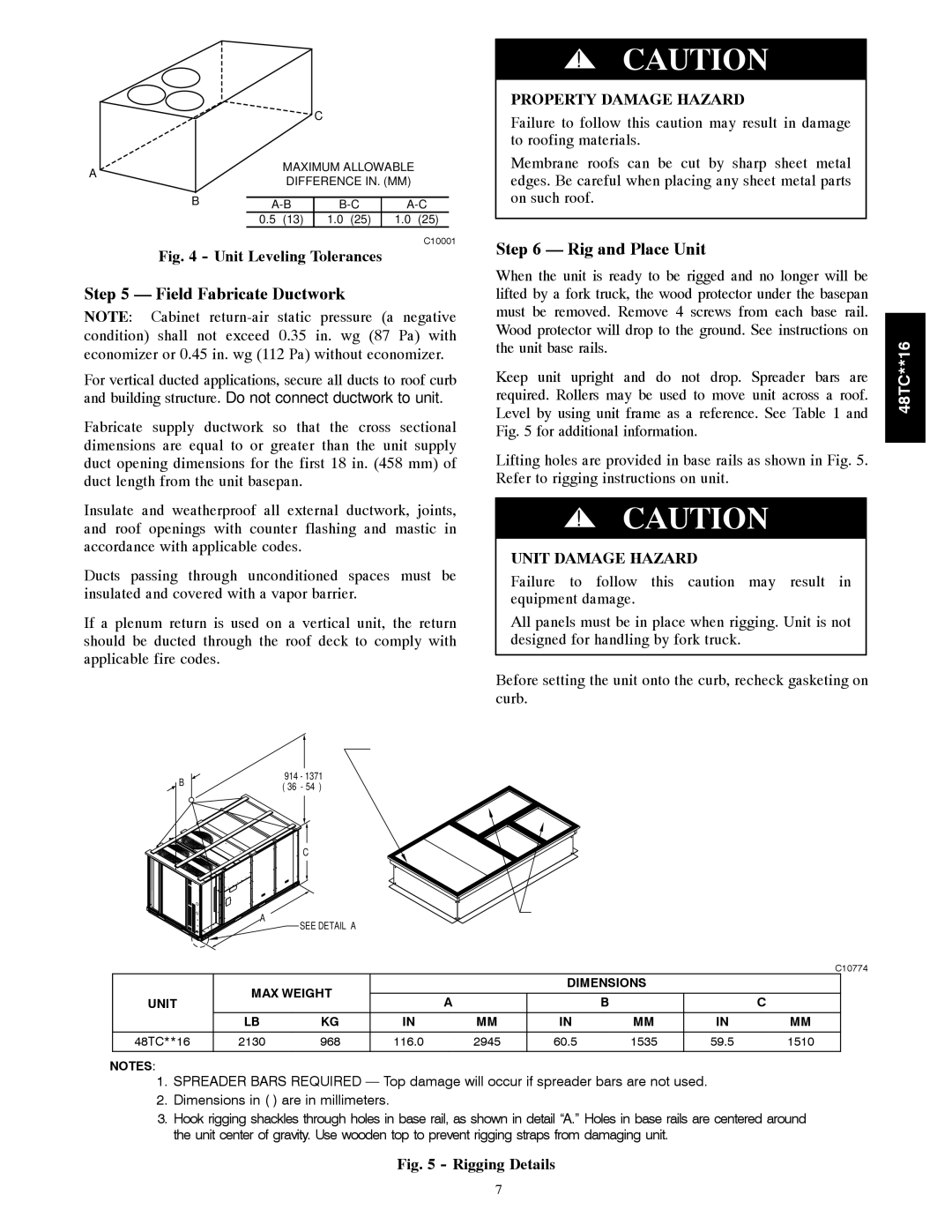
Fig. 4 - Unit Leveling Tolerances

Step 5 — Field Fabricate Ductwork

NOTE: Cabinet return-air static pressure (a negative condition) shall not exceed 0.35 in. wg (87 Pa) with economizer or 0.45 in. wg (112 Pa) without economizer.

For vertical ducted applications, secure all ducts to roof curb and building structure. Do not connect ductwork to unit.

Fabricate supply ductwork so that the cross sectional dimensions are equal to or greater than the unit supply duct opening dimensions for the first 18 in. (458 mm) of duct length from the unit basepan.

Insulate and weatherproof all external ductwork, joints, and roof openings with counter flashing and mastic in accordance with applicable codes.

Ducts passing through unconditioned spaces must be insulated and covered with a vapor barrier.

If a plenum return is used on a vertical unit, the return should be ducted through the roof deck to comply with applicable fire codes.

!CAUTION

PROPERTY DAMAGE HAZARD

Failure to follow this caution may result in damage to roofing materials.

Membrane roofs can be cut by sharp sheet metal edges. Be careful when placing any sheet metal parts on such roof.

Step 6 — Rig and Place Unit

When the unit is ready to be rigged and no longer will be lifted by a fork truck, the wood protector under the basepan must be removed. Remove 4 screws from each base rail. Wood protector will drop to the ground. See instructions on the unit base rails.

Keep unit upright and do not drop. Spreader bars are required. Rollers may be used to move unit across a roof. Level by using unit frame as a reference. See Table 1 and Fig. 5 for additional information.

Lifting holes are provided in base rails as shown in Fig. 5. Refer to rigging instructions on unit.

!CAUTION

UNIT DAMAGE HAZARD

Failure to follow this caution may result in equipment damage.

All panels must be in place when rigging. Unit is not designed for handling by fork truck.

Before setting the unit onto the curb, recheck gasketing on curb.

48TC**16

“B”

PLACE ALL SEAL STRIP IN PLACE BEFORE PLACING

UNIT ON ROOF CURB.

914 - 1371

( 36” - 54” )

“C”

“A”

DUCT END

DETAIL “A”

SEE DETAIL “A”

C10774


MAX WEIGHT


DIMENSIONS


UNIT


A


B


C


LB

KG

IN

MM

IN

MM

IN

MM


48TC**16

2130

968

116.0

2945

60.5

1535

59.5

1510


NOTES:

1.SPREADER BARS REQUIRED — Top damage will occur if spreader bars are not used.

2.Dimensions in ( ) are in millimeters.

3.Hook rigging shackles through holes in base rail, as shown in detail “A.” Holes in base rails are centered around the unit center of gravity. Use wooden top to prevent rigging straps from damaging unit.

Fig. 5 - Rigging Details

7

Page 7
Image 7
Carrier 48TC**16 Field Fabricate Ductwork, Rig and Place Unit, Property Damage Hazard, Unit Damage Hazard

48TC**16 specifications

The Carrier 48TC**16 is a high-efficiency rooftop packaged unit, designed for commercial heating and cooling applications. This model exemplifies Carrier's commitment to delivering reliable and innovative solutions to the HVAC industry. With cutting-edge technology and robust performance characteristics, the 48TC**16 is ideally suited for a variety of building types.

One of the main features of the Carrier 48TC**16 is its impressive energy efficiency. The unit achieves high SEER (Seasonal Energy Efficiency Ratio) ratings, which translates to lower energy bills and reduced environmental impact. The unit is equipped with a scroll compressor, known for its quiet operation and reliability, ensuring a comfortable indoor environment without disruptive noise.

The 48TC**16 utilizes advanced microprocessor controls that enhance system performance by enabling precise temperature control and various operational modes. This allows users to optimize the system's performance based on specific heating and cooling needs. Additionally, the unit includes enhanced diagnostics, allowing for faster troubleshooting and easier maintenance, thus minimizing downtime and repair costs.

Another notable characteristic of the 48TC**16 is its robust construction. Built to withstand harsh weather conditions, the unit features a galvanized steel cabinet coated with a corrosion-resistant finish, ensuring longevity and durability. It also comes equipped with a variety of factory-installed options, such as economizers and filtration systems, which can further enhance its performance and flexibility.

The Carrier 48TC**16 is designed with sustainability in mind, using environmentally friendly refrigerants. The unit supports the latest refrigerant regulations, helping to reduce the overall carbon footprint of the building it serves.

Installation and service are simplified by the unit's modular design, which allows for easy access to all major components. This design not only streamlines maintenance procedures but also facilitates quick installation, making it an ideal choice for contractors and facility managers alike.

In summary, the Carrier 48TC**16 rooftop packaged unit combines high energy efficiency, advanced controls, robust construction, and eco-friendly features, making it a top choice for commercial heating and cooling needs. Its user-friendly design and reliability ensure optimal performance and comfort for various applications, underscoring Carrier's reputation as a leader in the HVAC industry. Whether for new construction or retrofitting, the 48TC**16 meets the demands of modern buildings while adhering to sustainability practices.