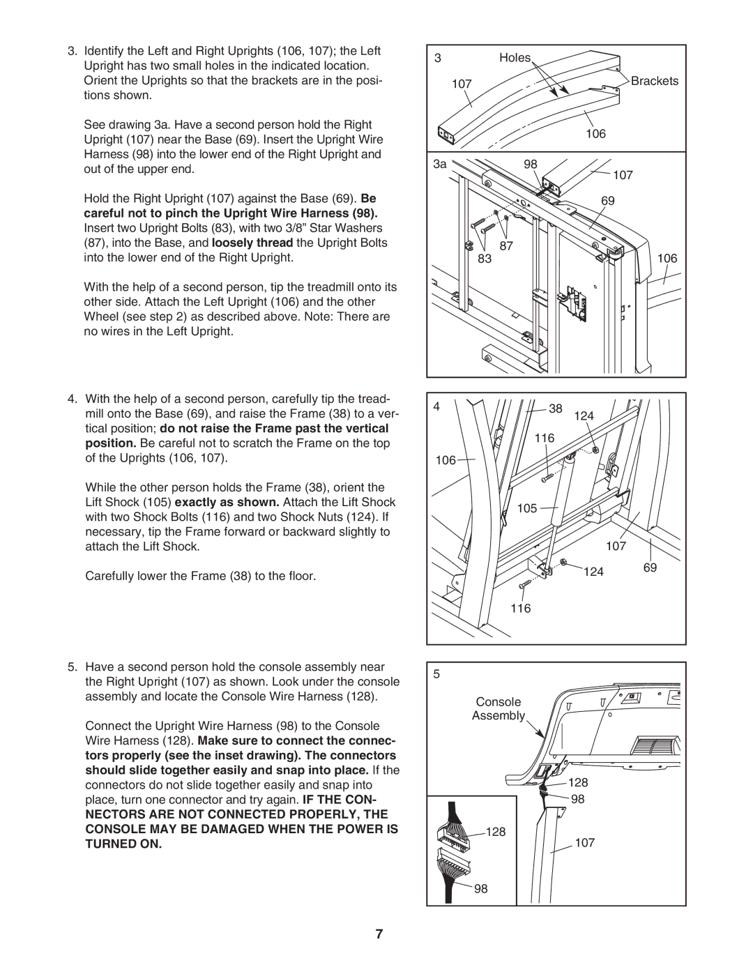
3.Identify the Left and Right Uprights (106, 107); the Left Upright has two small holes in the indicated location. Orient the Uprights so that the brackets are in the posi- tions shown.
See drawing 3a. Have a second person hold the Right Upright (107) near the Base (69). Insert the Upright Wire Harness (98) into the lower end of the Right Upright and out of the upper end.
Hold the Right Upright (107) against the Base (69). Be careful not to pinch the Upright Wire Harness (98). Insert two Upright Bolts (83), with two 3/8” Star Washers (87), into the Base, and loosely thread the Upright Bolts into the lower end of the Right Upright.
With the help of a second person, tip the treadmill onto its other side. Attach the Left Upright (106) and the other Wheel (see step 2) as described above. Note: There are no wires in the Left Upright.
4.With the help of a second person, carefully tip the tread- mill onto the Base (69), and raise the Frame (38) to a ver- tical position; do not raise the Frame past the vertical position. Be careful not to scratch the Frame on the top of the Uprights (106, 107).
While the other person holds the Frame (38), orient the Lift Shock (105) exactly as shown. Attach the Lift Shock with two Shock Bolts (116) and two Shock Nuts (124). If necessary, tip the Frame forward or backward slightly to attach the Lift Shock.
Carefully lower the Frame (38) to the floor.
5.Have a second person hold the console assembly near the Right Upright (107) as shown. Look under the console assembly and locate the Console Wire Harness (128).
Connect the Upright Wire Harness (98) to the Console Wire Harness (128). Make sure to connect the connec- tors properly (see the inset drawing). The connectors should slide together easily and snap into place. If the connectors do not slide together easily and snap into place, turn one connector and try again. IF THE CON-
NECTORS ARE NOT CONNECTED PROPERLY, THE CONSOLE MAY BE DAMAGED WHEN THE POWER IS TURNED ON.
3 | Holes |
|
|
107 |
|
| Brackets |
|
| 106 |
|
3a | 98 | 107 | |
|
| ||
|
| 69 |
|
83 | 87 |
| 106 |
|
| ||
4 | 38 | 124 |
|
|
| ||
| 116 |
|
|
106 |
|
|
|
| 105 |
|
|
|
| 107 |
|
|
| 124 | 69 |
|
|
| |
| 116 |
|
|
5 |
|
|
|
Console |
|
| |
Assembly |
|
| |
|
| 128 |
|
|
| 98 |
|
128 | 107 |
| |
|
|
| |
98 |
|
|
|
7