[4] | [6] | [9] |
PLEASE NOTE! The energy output is determined by the energy dials A and B. The energy out- put will remain consistent, regardless of which lamp sockets are used or the number of lamp heads connected to them. Energy dumping is not necessary as long as the dial MASTER is turned to MAX.
Energy Control
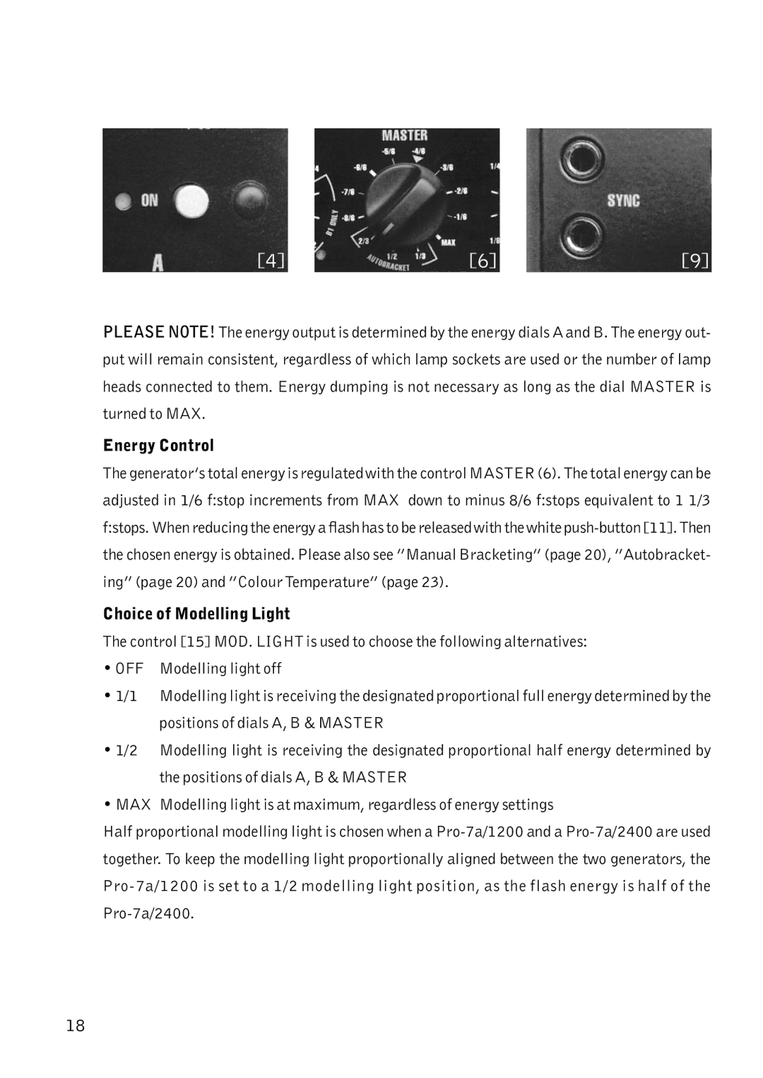
The generator’s total energy is regulated with the control MASTER (6). The total energy can be adjusted in 1/6 f:stop increments from MAX down to minus 8/6 f:stops equivalent to 1 1/3 f:stops. When reducing the energy a flash has to be released with the white
Choice of Modelling Light
The control [15] MOD. LIGHT is used to choose the following alternatives:
• OFF Modelling light off
•1/1 Modelling light is receiving the designated proportional full energy determined by the positions of dials A, B & MASTER
•1/2 Modelling light is receiving the designated proportional half energy determined by the positions of dials A, B & MASTER
•MAX Modelling light is at maximum, regardless of energy settings
Half proportional modelling light is chosen when a
18
