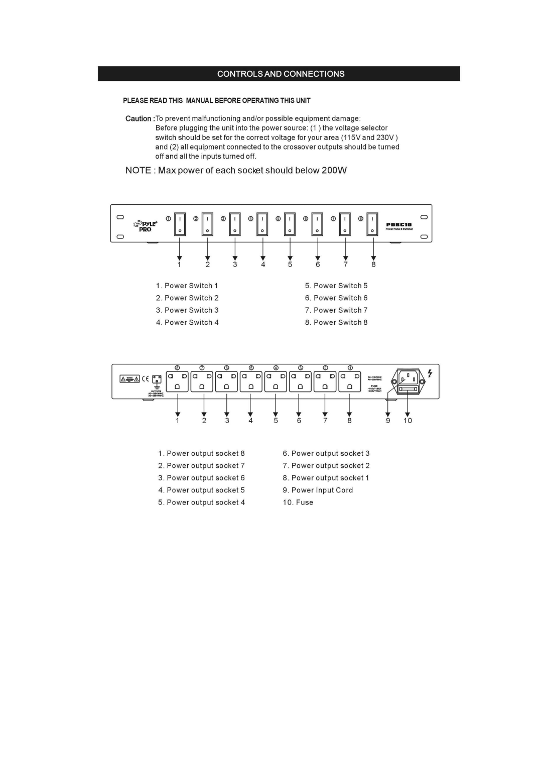
CONTROLS AND CONNECTIONS
PLEASE READ THIS MANUAL BEFORE OPERATING THIS UNIT
Caution :To prevent malfunctioning and/or possible equipment damage:
Before plugging the unit into the power source: (1 ) the voltage selector switch should be set for the correct voltage for your area (115Vand 230V) and (2) all equipment connected to the crossover outputs should be turned off and all the inputs turned off.
NOTE: Max power of each socket should below 200W
o |
|
|
|
|
|
| o |
o |
|
|
|
|
|
| o |
| 2 | 3 | 4 | 5 | 6 | 7 | 8 |
1. Power Switch 1 |
|
| 5. | Power Switch 5 |
| ||
2. | Power Switch 2 |
|
| 6. | Power Switch 6 |
| |
3. | Power Switch 3 |
|
| 7. | Power Switch 7 |
| |
4. | Power Switch 4 |
|
| 8. Power Switch 8 |
| ||
1&..&1 CE Ef la:°lla:°lla:°lla:°lla:°lla:°lla:°lla:°1
| 2 | 3 | 4 | 5 | 6 | 7 | 8 | 9 | 10 |
1. Power output socket 8 |
| 6. | Power output socket 3 |
|
| ||||
2. | Power output socket 7 |
| 7. | Power output socket 2 |
|
| |||
3. | Power output socket 6 |
| 8. | Power output socket 1 |
|
| |||
4. | Power output socket 5 |
| 9. | Power Input Cord |
|
| |||
5. | Power output socket 4 |
| 10. Fuse |
|
|
|
| ||
