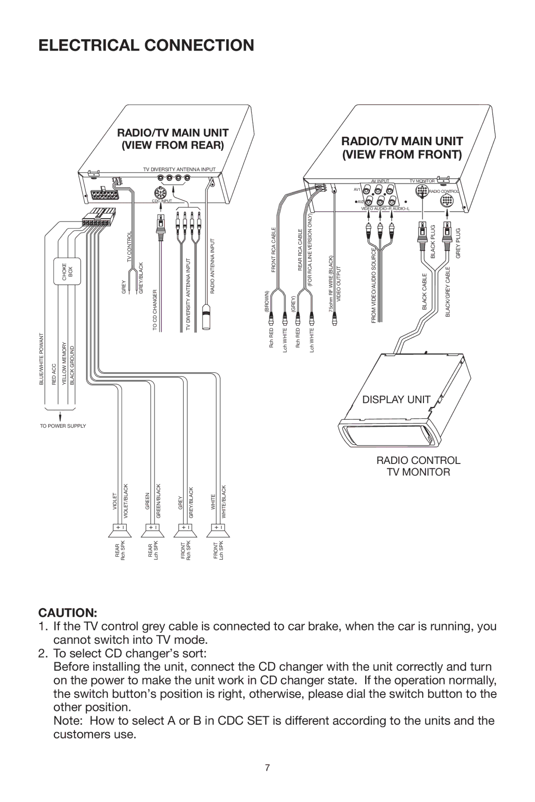
ELECTRICAL CONNECTION
|
|
|
| RADIO/TV MAIN UNIT | |||
|
|
|
| (VIEW FROM REAR) | |||
|
|
|
|
| TV DIVERSITY ANTENNA INPUT | ||
|
|
|
|
| CDC INPUT |
|
|
|
| CHOKE | BOX | GREY TV CONTROL GREY/BLACK | CD CHANGER | DIVERSITY ANTENNA INPUT | RADIO ANTENNA INPUT |
|
|
|
|
| TO | TV |
|
BLUE/WHITE POWANT | RED ACC | YELLOW MEMORY | BLACK GROUND |
|
|
|
|
TO POWER SUPPLY
VIOLET | VIOLET/BLACK | GREEN | GREEN/BLACK | GREY | GREY/BLACK | WHITE | WHITE/BLACK |
REAR | Rch SPK | REAR | Lch SPK | FRONT | Rch SPK | FRONT | Lch SPK |
RADIO/TV MAIN UNIT (VIEW FROM FRONT)
|
|
|
|
|
| AV INPUT | TV MONITOR |
|
| |
|
|
|
|
|
| AV1 |
| RADIO CONTROL | ||
|
|
|
|
|
|
|
| |||
|
|
|
|
|
| AV2 |
|
|
|
|
|
|
|
|
|
| VIDEO |
|
|
|
|
(BROWN) FRONT RCA CABLE | (GREY) | REAR RCA CABLE | (FOR RCA LINE VERSION ONLY) | 75ohm RF WIRE (BLACK) | VIDEO OUTPUT | FROM VIDEO/AUDIO SOURCE | BLACK CABLE | BLACK PLUG | BLACK/GREY CABLE | GREY PLUG |
Rch RED | Lch WHITE | Rch RED | Lch WHITE |
|
|
|
|
|
|
|
DISPLAY UNIT
RADIO CONTROL
TV MONITOR
CAUTION:
1.If the TV control grey cable is connected to car brake, when the car is running, you cannot switch into TV mode.
2.To select CD changer’s sort:
Before installing the unit, connect the CD changer with the unit correctly and turn on the power to make the unit work in CD changer state. If the operation normally, the switch button’s position is right, otherwise, please dial the switch button to the other position.
Note: How to select A or B in CDC SET is different according to the units and the customers use.
7
