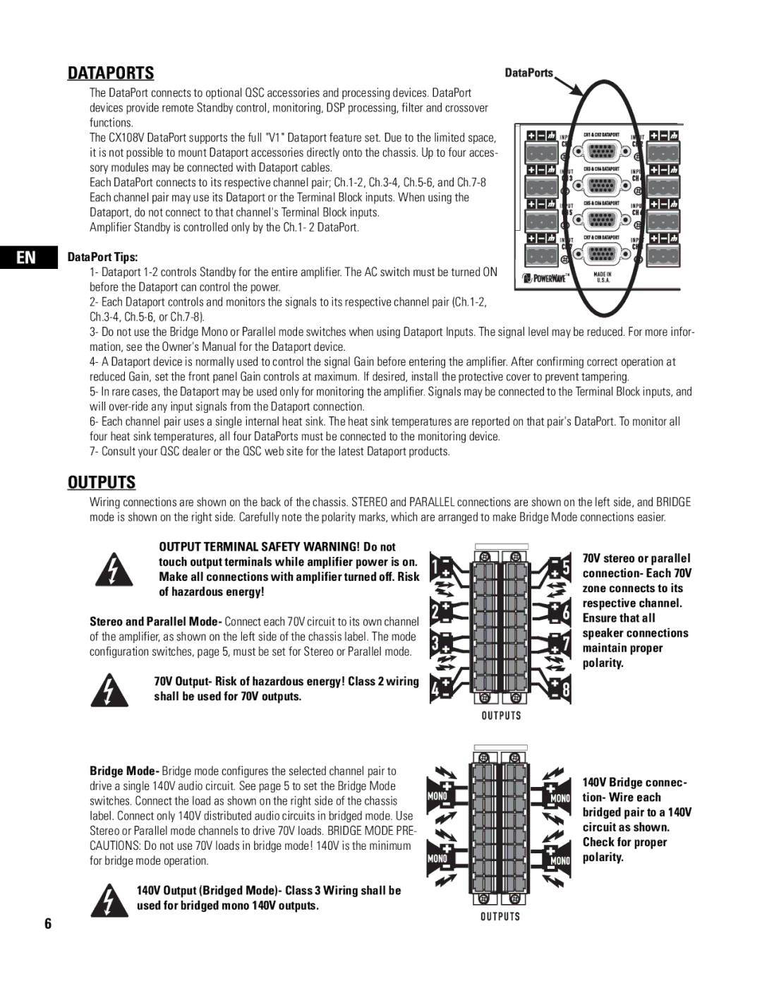
CX108V specifications
The QSC Audio CX108V is a powerful and versatile amplifier designed for commercial audio applications, particularly in environments such as retail spaces, restaurants, and other venues where high-quality sound is essential. Known for its reliability and performance, the CX108V has become a preferred choice for integrators and sound professionals alike.One of the main features of the CX108V is its ability to deliver high power output while maintaining exceptional audio quality. With a power rating of 1000 watts at 4 ohms, the amplifier is capable of driving a wide range of loudspeakers with ease. Its efficient Class D amplifier design ensures low heat generation and prolonged operational life, making it a perfect fit for installations that require continuous use.
Another notable characteristic of the CX108V is its lightweight and compact design, which simplifies the installation process. Weighing in at just 7.6 kg (16.8 lbs), the amplifier can be easily mounted in various locations, whether on a rack, shelf, or wall. This portability does not come at the expense of durability, as the chassis is built from robust materials to withstand the rigors of a commercial environment.
The CX108V is equipped with a range of input options, including balanced XLR and TRS connectors, allowing for easy integration with various audio sources. Additionally, the amplifier features a precision feedback circuitry that enhances its overall performance, ensuring consistent audio delivery even at high volumes. Built-in protections such as over-temperature and short-circuit protection ensure reliable operation, minimizing downtime in critical environments.
QSC’s advanced DSP technology further enhances the capabilities of the CX108V. The amplifier includes programmable signal processing features that allow for tailored audio management, including EQ settings, crossover adjustments, and delay configurations. This flexibility makes it suitable for a variety of installation scenarios, enabling sound professionals to fine-tune the audio experience to meet specific needs.
In summary, the QSC Audio CX108V is a remarkable amplifier that combines power, efficiency, and intelligibility. Its lightweight design, robust protection features, and advanced DSP capabilities make it a go-to choice for audio professionals seeking high-performance solutions for commercial audio applications. With the CX108V, QSC Audio continues its tradition of delivering products that not only meet but exceed expectations in sound quality and reliability.

