StorNext File System Tuning
The Distributed LAN (Disk Proxy) Networks
Network Configuration and Topology
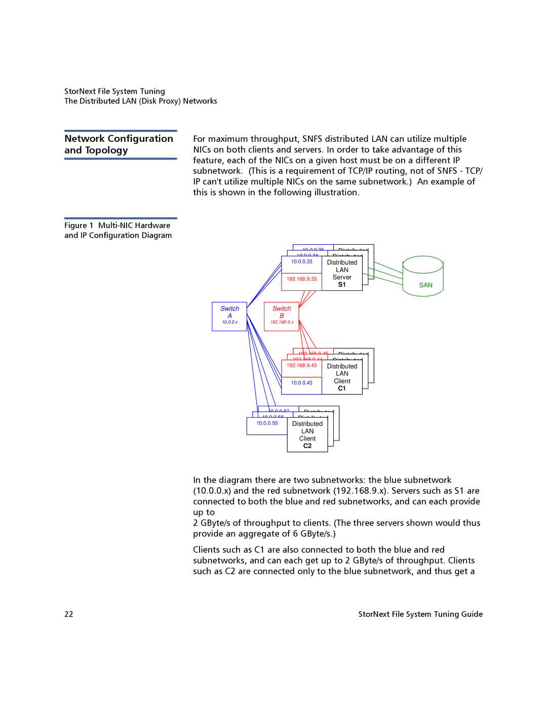
Figure 1 Multi-NIC Hardware and IP Configuration Diagram
For maximum throughput, SNFS distributed LAN can utilize multiple NICs on both clients and servers. In order to take advantage of this feature, each of the NICs on a given host must be on a different IP subnetwork. (This is a requirement of TCP/IP routing, not of SNFS - TCP/ IP can't utilize multiple NICs on the same subnetwork.) An example of this is shown in the following illustration.
10.0.0.35 |
| Distributed |
|
10.0.0.34 |
| Distributed |
|
10.0.0.33 |
| LAN |
|
Distributed |
| ||
|
| LAN |
|
192.168.9.35 | Server |
| |
LAN |
| ||
192.168.9.34 |
| Server |
|
| S1 |
| |
192.168.9.33 |
| Server |
|
| S1 | SAN | |
|
| S1 | |
Switch | Switch |
AB
10.0.0.x | 192.168.9.x |
192.168.9.45 | Distributed | |
192.168.9.44 |
| Distributed |
192.168.9.43 |
| LAN |
Distributed | ||
|
| LAN |
10.0.0.45 |
| Client |
| LAN | |
|
| Client |
10.0.0.44 |
| ClientC1 |
10.0.0.43 |
| C1 |
|
| C1 |
10.0.0.57 ![]() Distributed
Distributed
10.0.0.56 Distributed
10.0.0.55LAN
Distributed
LAN
Client
LAN
Client
ClientC2
C2
C2
In the diagram there are two subnetworks: the blue subnetwork (10.0.0.x) and the red subnetwork (192.168.9.x). Servers such as S1 are connected to both the blue and red subnetworks, and can each provide up to
2 GByte/s of throughput to clients. (The three servers shown would thus provide an aggregate of 6 GByte/s.)
Clients such as C1 are also connected to both the blue and red subnetworks, and can each get up to 2 GByte/s of throughput. Clients such as C2 are connected only to the blue subnetwork, and thus get a
22 | StorNext File System Tuning Guide |