4.5 Options Register
The Options Register allows software to identify the
The powerup default of the Options Register is all bits zero.
Bit | Name | Description |
|
|
|
7 (MSB) | ID1 | ID bit 1 |
|
|
|
6 | ID0 | ID bit 0 |
|
|
|
5 | - | (reserved, 0) |
|
|
|
4 | - | (reserved, 0) |
|
|
|
3 | - | (reserved, 0) |
|
|
|
2 | - | (reserved, 0) |
|
|
|
1 | RR1 | Clock rate multiplier bit 1 |
|
|
|
0 | RR0 | Clock rate multiplier bit 0 |
|
|
|
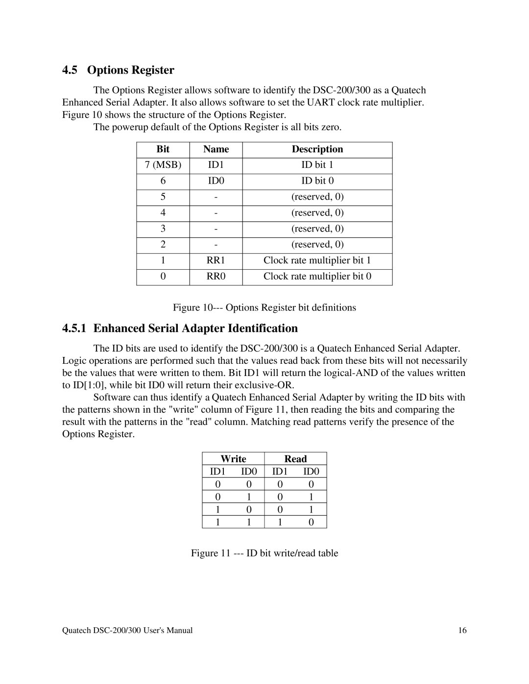
Figure 10--- Options Register bit definitions
4.5.1 Enhanced Serial Adapter Identification
The ID bits are used to identify the
Software can thus identify a Quatech Enhanced Serial Adapter by writing the ID bits with the patterns shown in the "write" column of Figure 11, then reading the bits and comparing the result with the patterns in the "read" column. Matching read patterns verify the presence of the Options Register.
Write | Read | ||
ID1 | ID0 | ID1 | ID0 |
0 | 0 | 0 | 0 |
0 | 1 | 0 | 1 |
1 | 0 | 0 | 1 |
1 | 1 | 1 | 0 |
Figure 11 --- ID bit write/read table
Quatech | 16 |