FUNCTION OVERVIEW |
1-2 SPECIFICATIONS
Connector | A 4 terminal block | |
| and | |
|
| |
|
| TAB** |
|
| |
| SWl:DCE,DTE, MONITOR* | |
| selection | |
Function Switch | SW2:TxON. | RxON |
| SW2:TxRTS, | RXXrt |
| SW2:TxRTS. RxON | |
Enclosure | Plastic |
|
Weight | 60 gm |
|
Dimensions | 54x74.5x18.5mm | |
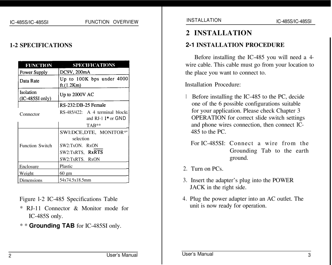
Figure l-2 IC-485 Specifications Table
*RJ-11 Connector & Monitor mode for IC-485S only.
** Grounding TAB for IC-485SI only.
2 | User’s Manual |
INSTALLATIONIC-485S/IC-485SI
2 INSTALLATION
2-1 INSTALLATION PROCEDURE
Before installing the
Installation Procedure:
1Before installing the
For
2.Turn on PCs.
3.Insert the adapter’s plug into the POWER JACK in the right side.
4.Plug the power adapter into an AC outlet. The unit is now ready for operation.
User’s Manual | 3 |