| |||||||
PLEX | A |
| B |
| |||
r/ |
|
|
| ||||
T+I |
| IR+ | / | ||||
| |||||||
|
|
|
|
|
|
| |
|
|
|
|
|
|
|
|
| I |
|
|
|
| ||
|
|
|
|
|
| Configuration: | |
Configuration: |
|
|
|
| |||
A1 DCWJITE ) TxON,RxON
B1 DCE/DTE ) TxON,RxON
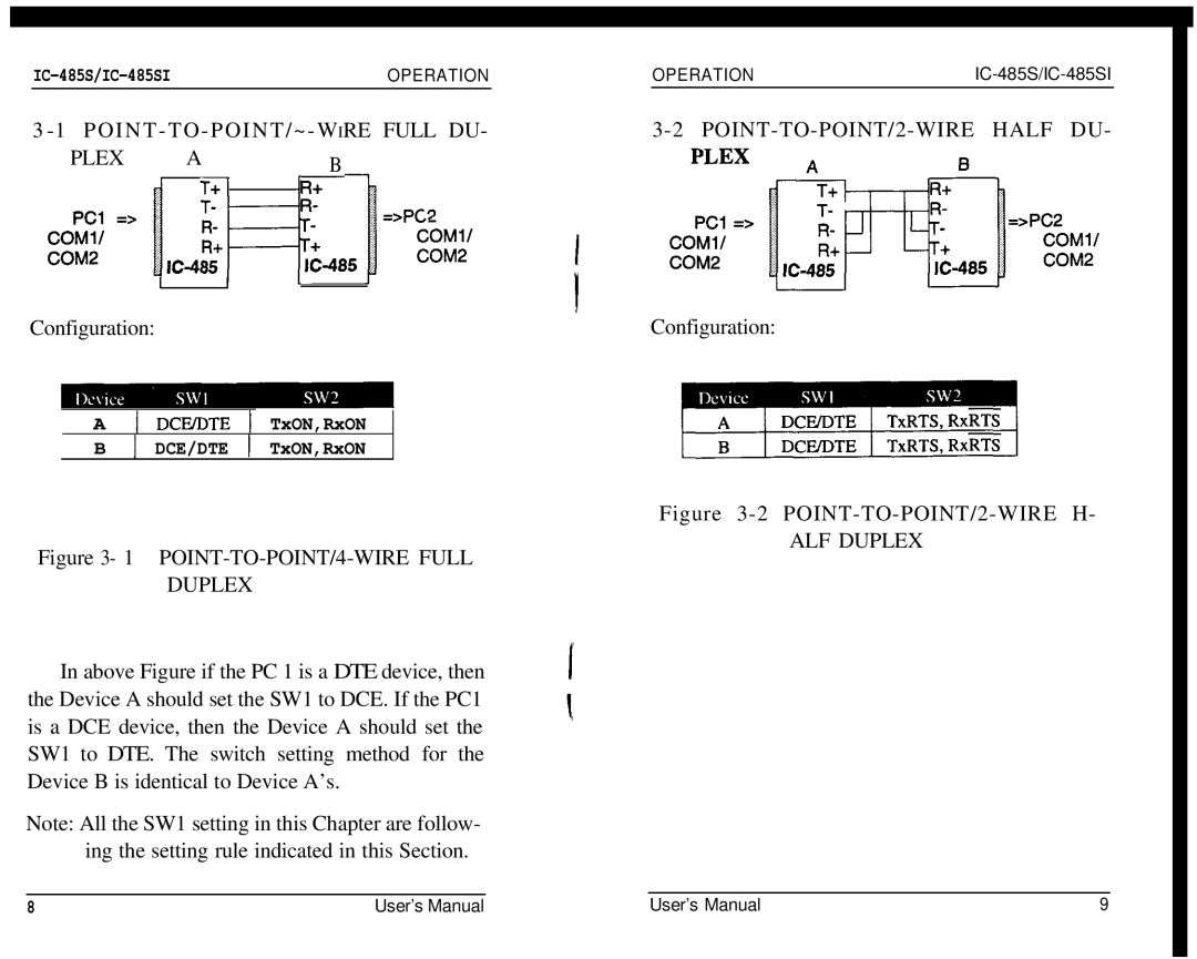
Figure 3-2 POINT-TO-POINT/2-WIRE H-
ALF DUPLEX
Figure 3- 1 POINT-TO-POINT/4-WIRE FULL
DUPLEX
In above Figure if the PC 1 is a DTE device, then the Device A should set the SW1 to DCE. If the PC1 is a DCE device, then the Device A should set the SW1 to DTE. The switch setting method for the Device B is identical to Device A’s.
Note: All the SW1 setting in this Chapter are follow- ing the setting rule indicated in this Section.
8 | User’s Manual | User’s Manual | 9 |
