
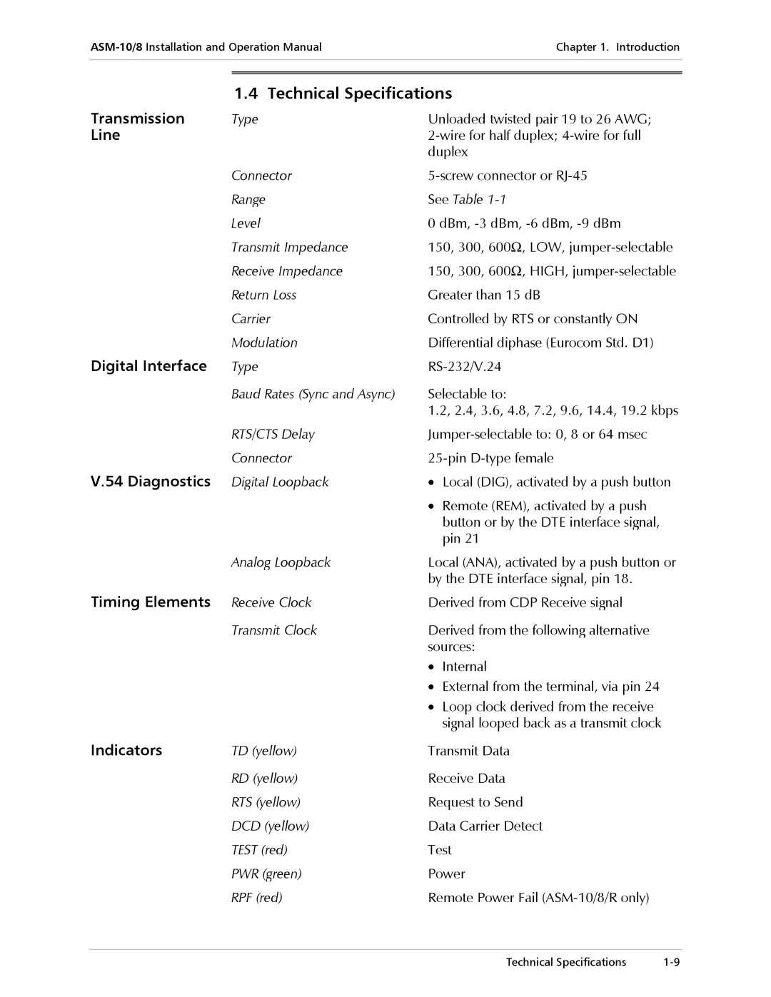
ASM-10/8 specifications
The RAD DataComm ASM-10/8 is a versatile and robust network access and service management solution designed for telecom operators and service providers. It serves as an essential tool for enhancing the efficiency and performance of data communication networks, particularly in environments that require high reliability and real-time service delivery.One of the key features of the ASM-10/8 is its ability to seamlessly integrate with various existing network infrastructures. This flexibility allows operators to bolster their services without the need for a complete overhaul of their systems. The ASM-10/8 supports multiple protocols, making it compatible with a wide range of technologies, including Ethernet, T1/E1, and more, ensuring that it can be used effectively in diverse scenarios.
The ASM-10/8 is characterized by its advanced management capabilities. It comes equipped with a powerful network management system that enables real-time monitoring and configuration of network elements. This functionality provides operators with significant insights into network performance, enabling them to address issues proactively and maintain consistent service quality.
In terms of scalability, the ASM-10/8 is designed to accommodate growing network demands. Its modular architecture allows for easy upgrades and expansions, enabling service providers to quickly adapt to changing requirements. This scalability is particularly important in today’s fast-paced digital landscape, where the ability to provide additional bandwidth or services can be a competitive advantage.
Security is another critical aspect of the ASM-10/8. The device integrates robust security features, including encryption and access controls, ensuring that sensitive data is protected. This focus on security not only safeguards customer information but also helps maintain compliance with regulatory standards.
Moreover, the ASM-10/8 supports a range of advanced technologies such as Quality of Service (QoS) mechanisms, which prioritize traffic to ensure that critical applications receive the necessary bandwidth. This capability is essential for delivering high-quality services, especially in environments with heavy data traffic.
In conclusion, the RAD DataComm ASM-10/8 represents a powerful solution for modern telecom operators and service providers. Its combination of flexibility, scalability, robust management capabilities, and security features make it an ideal choice for organizations looking to enhance their data communication services. With the ability to adapt to evolving technologies and customer needs, the ASM-10/8 is poised to support the growth and success of network operators in an increasingly digital world.