4-channel surveillance controller
Thank you for purchasing your
Its features include:
Automatic VCR Record – automatically actives when PIR has been triggered.
Intercom Function – enables
Auto and Manual Scan Function – automatically scans and displays each channel after you power the controller each time, and you also can scan the channels manually.
Inline Audio Buzzer Warning – activates the buzzer when the unit is triggered if you set the alarm on.
IR (infrared) cable | |
| 15V AC adapter |
You can power the controller using the supplied 15V, 850mA AC/DC adapter.
| Always connect the adapter to your controller before you connect it to AC power. When you finish, |
Notes | disconnect the adapter from AC power before you disconnect it from the controller. |
The AUTO/MANUAL indicator lights when you power the controller. The unit automatically enters the auto- scan mode and sounds two beeps after you complete the connection.
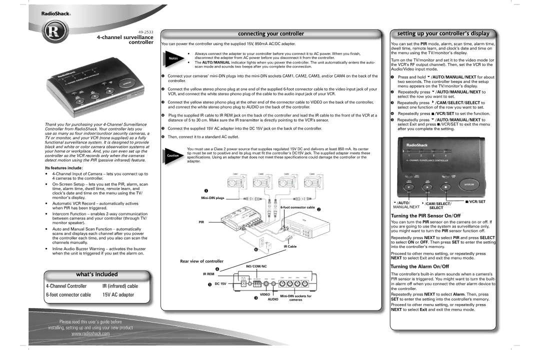
Connect your cameras’
Connect the yellow stereo phono plug at one end of the supplied
Connect the yellow stereo phono plug at the other end of the connector cable to VIDEO on the back of the controller, and connect the white stereo phono plug to AUDIO on the back of the controller.
Plug the supplied IR cable to IR REM jack on the back of the controller and lead the IR cable to the front of the VCR at a distance of 5 to 30 cm. Make sure the IR transmitter is directly pointing to the VCR’s sensor.
Connect the supplied 15V AC adapter into the DC 15V jack on the back of the controller.
Then, connect it to a standard AC outlet.
You must use a Class 2 power source that supplies regulated 15V DC and delivers at least 850 mA. Its center
tip must be set to positive and its plug must fit the controller’s DC15V jack. The supplied adapter meets these
Caution specifications. Using an adapter that does not meet these specifications could damage the controller or the adapter.
PIR
IR Cable
Rear view of controller
NO/COM/NC
IR REM
DC 15V
VIDEO | ||
AUDIO | ||
cameras |
You can set the PIR mode, alarm, scan time, alarm time, dwell time, remote learn, and clock’s date and time on the menu using the TV/monitor’s display.
Turn on the TV/monitor and set it to the video mode (or the VCR’s RF output channel). Then, set the VCR to the Audio/Video input mode.
Press and hold 6/AUTO/MANUAL/NEXT for about two seconds. The controller beeps and the setup menu appears on the TV/monitor’s display.
Repeatedly press 6/AUTO/MANUAL/NEXT to select the row you want to set.
Repeatedly press 4/CAM/SELECT/SELECT to select one function of the row you want to set.
Repeatedly press ![]() /VCR/SET to set the function.
/VCR/SET to set the function.
Repeatedly press 6/AUTO/MANUAL/NEXT to select Exit and press ![]() /VCR/SET to exit the menu after you complete the setting.
/VCR/SET to exit the menu after you complete the setting.
6/AUTO/ 4/CAM/SELECT/ ![]() /VCR/SET
/VCR/SET
MANUAL/NEXT SELECT
Turning the PIR Sensor On/Off
You can turn the PIR sensor on the camera on or off. If you are going to use the system as surveillance only, you might want to turn the PIR sensor function off.
Repeatedly press NEXT to select PIR and press SELECT to select ON or OFF. Then press SET to enter the setting into the controller’s memory.
Proceed to other menu setting, or repeatedly press NEXT to select Exit and exit the menu mode.
Turning the Alarm On/Off
The controller's
Repeatedly press NEXT to select Alarm. Then, press SET to enter the setting into the controller's memory. Proceed to other menu setting, or repeatedly press NEXT to select Exit and exit the menu mode.
Please read this user’s guide before
installing, setting up and using your new product
www.radioshack.com