HUE
It is for adjusting the hue of the video output.
SATURATION
It is for adjusting the saturation of the video output.
SHARPNESS
It is for adjusting the sharpness of the video output.
5.19.5 SPEAKER SETUP
SPEAKER SETUP
DOWNMIX
EXIT SETUP
DOWNMIX
It is for selecting your desired sound effect when there is not central speaker and
LT/RT: When playing a disc with PRO LOGIC Dolby stereo effect, choose the item, so it will output audio signal with vivid theatre effect.
STEREO: If you choose the item, when outputting audio signal with 5.1 channels, it will output the left and right channels of signal ; when outputting audio signal with 2 channels, it will output the common 2 channels of stereo signal.
VSS: If you choose the item, when playing a disc recorded with 5.1 channels, the main channel speakers can output audio signal with VSS effect.
5.l9.6 DIGITAL SETUP
DIGITAL SETUP
OP MODE
DYNAMIC RANGE
DUAL MONO
EXIT SETUP
OP MODE
It is for selecting audio output mode
LINE OUT: It can linearly compress the audio signal. So the volume level is lower. You should select the item at night.
RF REMOD: It can make the volume level higher. You should select it at daylight.
DYNAMIC RANGE
After selecting the compression mode of LINE OUT, set the item, so you can adjust the linear compression ratio. If you set it to be FULL, the
DUAL MONO
It is for selecting a desired audio output mode for the left and right ways of signal. It is mainly for Karaoke of Ac3. There are 4 modes in all as follows:
STEREO, MONO L, MONO R, MIX MONO.
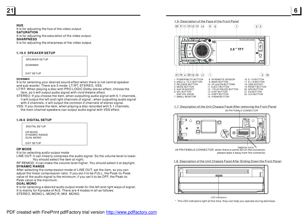
1.6 Description of the Face of the Front Panel
22 | 9 | 11 | 10 12 | 13 | 14 | 8 | 6 | 7 | 5 | 2 |
| 1 | 2 INT | 3 RPT | DVD/VCD/CD/MP3/USB/MMC | ANG |
|
| ||||
|
|
|
|
| USB |
BND |
|
| _ |
|
|
| UP |
| 3.8 " TFT |
| |
CLK |
|
|
| ||
|
|
|
| ||
|
|
| SEL |
| |
EQ | DN |
| + |
|
|
APS |
|
|
| ||
|
|
|
|
| |
|
|
|
|
| AUX |
|
|
| MU |
|
|
MODE | 4 RDM | 5 | 6 +10 |
| REL |
21 19 | 4 | 20 15 | 16 | 17 | 1 |
|
| 3 | 18 |
1. POWER/MUTE BUTTON | 8. IR REMOTE SENSOR | 16. |
| ||||||
2. ANG(i.e. TILT) BUTTON | 9. BAND BUTTON | 17. | 6/+10 BUTTON |
| |||||
3. RELEASE BUTTON |
| 10. UP and DN BUTTONS | 18. USB SOCKET |
| |||||
4. MODE BUTTON |
|
| 11. EJECT BUTTON | 19. RESET BUTTON | |||||
5. AUX IN SOCKET |
|
| 12. | 1/PLAY/PAUSE BUTTON | 20. APS BUTTON |
| |||
6. SEL BUTTON |
|
| 13. | 2/INT BUTTON | 21. EQ BUTTON |
| |||
AND VOL KNOB |
|
| 14. | 3/RPT BUTTON | 22. CLK BUTTON |
| |||
7. SMALL MONITOR |
| 15. | 4/RDM BUTTON |
|
|
| |||
1.7 Description of the Unit Chassis Facet After removing the Front Panel
26 PIN FEMALE CONNECTOR
26 PIN FEMALE CONNECTOR: when there is some dirt on the connector, please wipe it away from the connector.
1.8 Description of the Unit Chassis Facet After Sliding Down the Front Panel
LED indicators
* The LED indicators light all the time, they can help you operate during darkness.
PDF created with FinePrint pdfFactory trial version http://www.pdffactory.com
