CONTENTS, DESCRIPTION & ASSEMBLY INSTRUCTIONS

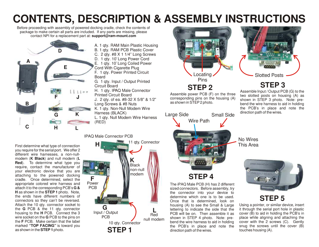
Before proceeding with assembly of powered docking cradle, check the contents of package to make certain all parts are included. If any parts are missing, please contact NPI for a replacement part at: support@ram-mount.com


A. 1 qty. RAM Main Plastic Housing


D


B. 1 qty. RAM PCB Plastic Cover


C. 2 qty. #8 X 1 1/4” Long Screws

A


D. 1 qty. 10’ Long Power Cord

E


E. 1 qty. 10’ Long Coiled Power


Cord With Cigarette Plug


F. 1 qty. Power Printed Circuit


Board


G. 1 qty. Input / Output Printed


Circuit Board


H. 1 qty. IPAQ Male Connector


F

J

Printed Circuit Board

B

J. 2 qty. of ea. #8-32 X 5/8” & 1/2”


Long Screws & #8 Nuts


K. 1 qty. Non-Null Modem Wire


G

K

Harness (BLACK)


L. 1 qty. Null Modem Wire Harness


C

H


(RED)

L


Locating

Pins

STEP 2

Assemble power PCB (F) on the three corresponding pins on the housing (A) as shown in STEP 2 photo.

Large Side

Small Side

Wire Path

Slotted Posts

STEP 3

Assemble Input / Output PCB (G) to the two slotted posts on housing (A) as shown in STEP 3 photo. Note: pre- bend the wire harness to aid in holding the PCB’s in place and note the direction path of the wires.

IPAQ Male Connector PCB

No Wires

First determine what type of connection you require for the serial port. We offer 2 different wire harnesses, a non-null- modem (K Black) and null modem (L Red). To determine what type you

H

11 qty. Connector

K

This Area

require, contact the manufacturer of your electronic device that you are attaching to the powered docking cradle. Once determined, select the appropriate colored wire harness and attach it to the corresponding PCB’s G & H as shown in the STEP 1 photo. Note, the ends have different numbers of connectors so they can’t be reversed.

F

Power

PCB

Black non-null modem

STEP 4

The iPAQ Male PCB (H) has 2 different sized connectors. Before assembly, try the connector into your device to determine which one is to be used. Once that is determined, look on

STEP 5

Attach the 10 qty. connector socket to the G PCB & the 11 qty. connector housing to the H PCB. Connect the 3 wire socket on the G PCB to the pins on the F PCB. Make certain that the label marked “TOP FACING” is toward you as shown in the STEP 1 photo.

G

Input / OutputL Red

PCB

null modem

10 qty. Connector

STEP 1

housing (A) to see the Small & Large lettering to indicate the side that the PCB will be on. Then assemble it as shown in STEP 4 photo. Note: pre- bend the wire harness to aid in holding the PCB’s in place and note the direction path of the wires.

Using a pointer, or similar device, insert it through the serial port hole in plastic cover (B) to aid in holding the PCB’s in place while aligning and attaching the cover with the 2 screws (C). Gently snug the screws until the cover (B) touches housing (A).

Page 2
Image 2
RAM Mounting Systems 3900, 3800, 3600, 5500, 3100, 5400, 3700 manual CONTENTS, Description & Assembly Instructions

5500, 3800, 3100, 3900, 3700 specifications

RAM Mounting Systems are renowned for their exceptional versatility and durability, making them ideal for various applications, from marine to automotive to industrial use. The models 3600, 3700, 3900, 5400, and 3100 represent a range of innovative features and technologies that enhance usability and performance across different environments.

The RAM 3600 series is designed for heavy-duty applications. It offers an impressive load capacity and features a unique ball and socket mounting system, allowing for a wide range of motion and positioning. This adjustability ensures that devices can be securely positioned for optimal viewing and accessibility. Constructed from high-strength composites and aluminum, the 3600 series is resistant to corrosion, making it suitable for marine environments.

The RAM 3700 series builds on this foundation, integrating an advanced locking mechanism that secures devices in place regardless of the terrain. This model is particularly popular in off-road and rugged applications, where stability is essential. The 3700 series also features adjustable arms, allowing for customization based on specific needs, ensuring that equipment remains secure during travel.

The RAM 3900 series is tailored for the tech-savvy user. It supports a variety of devices including tablets and smartphones, and its modular design allows for quick attachment and detachment of devices. This flexibility is complemented by a sleek aesthetic, making it ideal for professional settings. The 3900 series incorporates shock-absorbing technology, which protects sensitive devices from bumps and vibrations.

The RAM 5400 series emphasizes strength and reliability. Designed for industrial use, it meets rigorous safety standards and offers enhanced load-bearing capacity. Its robust construction ensures that it can handle not only electronic devices but also tools and equipment in demanding environments. This series is equipped with a quick-release mechanism for convenient device changes without compromising security.

Lastly, the RAM 3100 series focuses on lightweight applications while maintaining the hallmark durability of RAM products. It features a compact design that is perfect for smaller devices, making it an excellent choice for personal and light commercial use. The 3100’s simplistic design does not sacrifice strength and allows for user-friendly installations and adjustments.

In summary, RA Mounting Systems’ 3600, 3700, 3900, 5400, and 3100 models each offer unique features and technologies tailored to different needs. With a combination of adjustability, strength, and ease of use, these mounting systems ensure that devices are securely held in place across a wide range of applications. Whether in a vehicle, on a boat, or at a job site, RAM Mounting Systems provide reliable solutions that enhance productivity and safety.