1. Carefully “tin” the center conductor of the cable by adding a small amount of solder to the twisted center conductor. Use care not to leave the soldering iron in contact with the wire for too long as it can melt the center insulation. Tinning allows us easier installation of the coaxial cable to the circuit board assembly and minimizes the chance of overheating the wire when this installation occurs. Have a look at the diagram to see what the complete
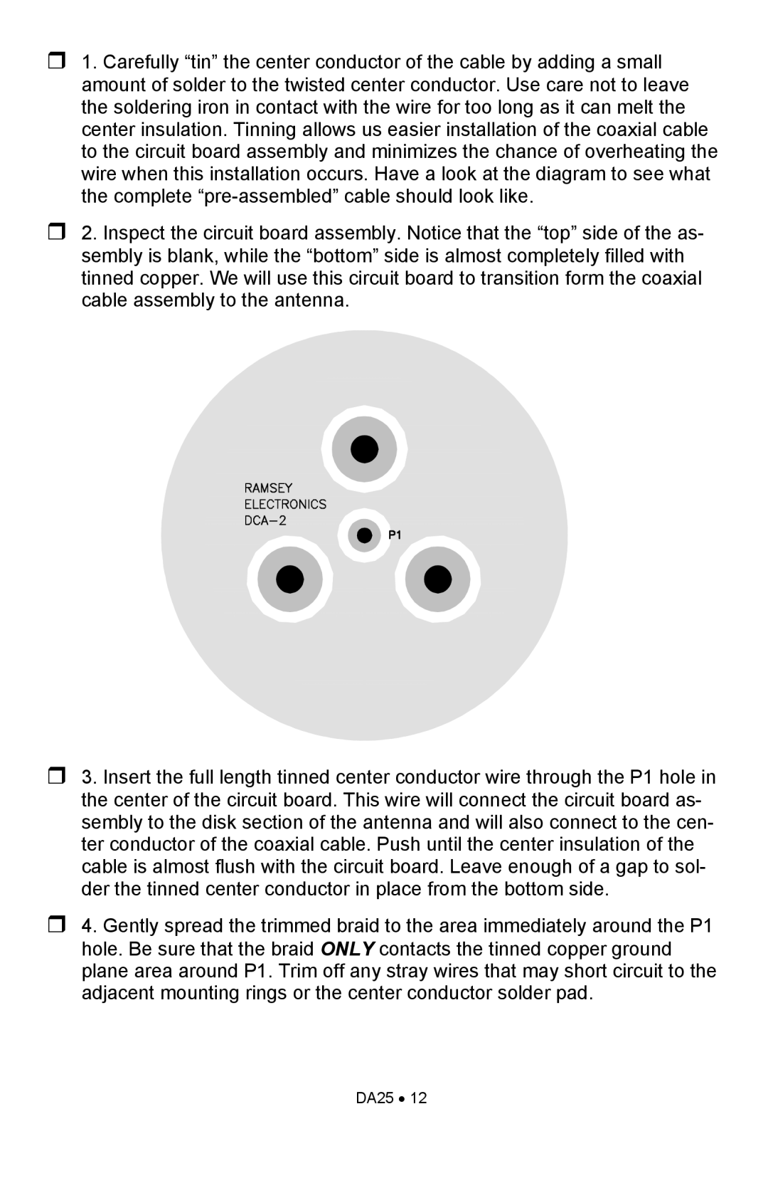
2. Inspect the circuit board assembly. Notice that the “top” side of the as- sembly is blank, while the “bottom” side is almost completely filled with tinned copper. We will use this circuit board to transition form the coaxial cable assembly to the antenna.
3. Insert the full length tinned center conductor wire through the P1 hole in the center of the circuit board. This wire will connect the circuit board as- sembly to the disk section of the antenna and will also connect to the cen- ter conductor of the coaxial cable. Push until the center insulation of the cable is almost flush with the circuit board. Leave enough of a gap to sol- der the tinned center conductor in place from the bottom side.
4. Gently spread the trimmed braid to the area immediately around the P1 hole. Be sure that the braid ONLY contacts the tinned copper ground plane area around P1. Trim off any stray wires that may short circuit to the adjacent mounting rings or the center conductor solder pad.