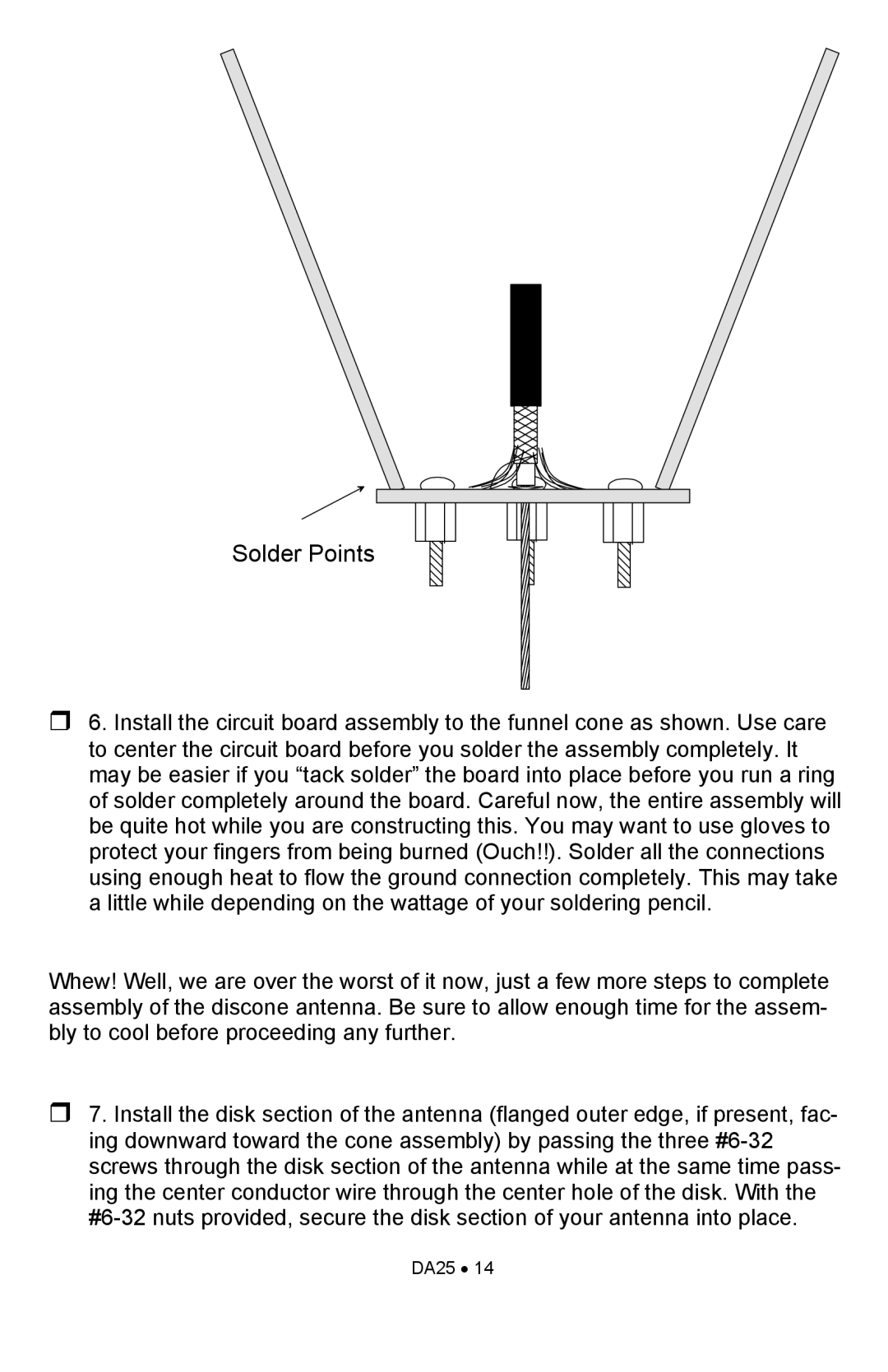
Solder Points
6. Install the circuit board assembly to the funnel cone as shown. Use care to center the circuit board before you solder the assembly completely. It may be easier if you “tack solder” the board into place before you run a ring of solder completely around the board. Careful now, the entire assembly will be quite hot while you are constructing this. You may want to use gloves to protect your fingers from being burned (Ouch!!). Solder all the connections using enough heat to flow the ground connection completely. This may take a little while depending on the wattage of your soldering pencil.
Whew! Well, we are over the worst of it now, just a few more steps to complete assembly of the discone antenna. Be sure to allow enough time for the assem- bly to cool before proceeding any further.
7. Install the disk section of the antenna (flanged outer edge, if present, fac- ing downward toward the cone assembly) by passing the three