right, you can do it with the rest. These will all be mounted in
23. Install D5 through D9. Be sure you solder them all.
24. Install D10 through D14. Notice that the orientation has changed.
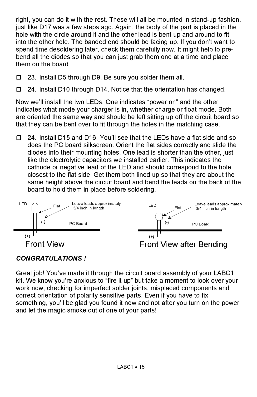
Now we’ll install the two LEDs. One indicates “power on” and the other indicates what mode your charger is in, whether charge or float mode. Both are oriented the same way and should be left sitting up off the circuit board so that they can be bent over to fit through the holes in the matching case.
24. Install D15 and D16. You’ll see that the LEDs have a flat side and so does the PC board silkscreen. Orient the flat sides correctly and slide the diodes into their mounting holes. One lead is shorter than the other, just like the electrolytic capacitors we installed earlier. This indicates the cathode or negative lead of the LED and should correspond to the hole closest to the flat side. Get them both lined up so that they are about the same height above the circuit board and bend the leads on the back of the board to hold them in place before soldering.
LED |
| Flat | Leave leads approximately | LED | Flat | Leave leads approximately |
|
| 3/4 inch in length | 3/4 inch in length | |||
|
|
|
| |||
|
|
|
|
|
|
|
PC Board
PC Board
Front View | Front View after Bending |
CONGRATULATIONS !
Great job! You’ve made it through the circuit board assembly of your LABC1 kit. We know you’re anxious to “fire it up” but take a moment to look over your work now, checking for imperfect solder joints, misplaced components and correct orientation of polarity sensitive parts. Even if you have to fix something, you’ll be glad you found it now and not after you turn on the power and let the magic smoke out of one of your parts!
