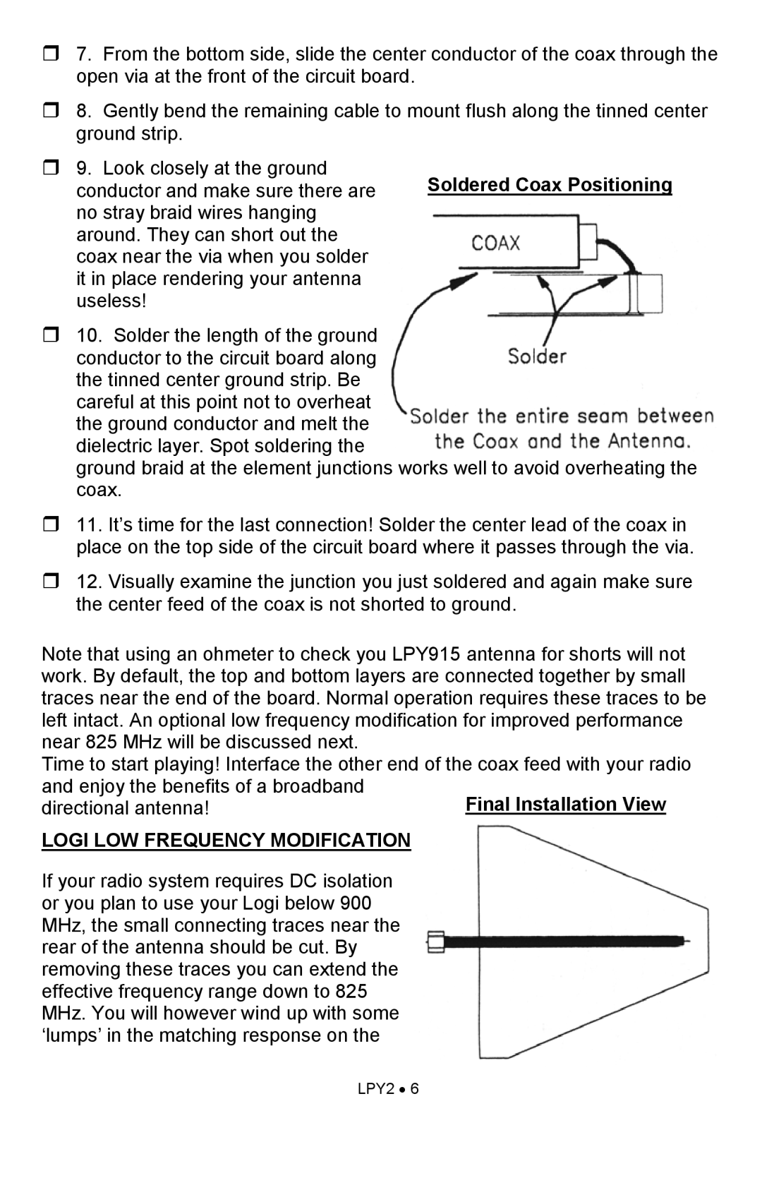
7. From the bottom side, slide the center conductor of the coax through the open via at the front of the circuit board.
8. Gently bend the remaining cable to mount flush along the tinned center ground strip.
9. Look closely at the ground
conductor and make sure there are Soldered Coax Positioning no stray braid wires hanging
around. They can short out the coax near the via when you solder it in place rendering your antenna useless!
10. Solder the length of the ground conductor to the circuit board along the tinned center ground strip. Be careful at this point not to overheat the ground conductor and melt the dielectric layer. Spot soldering the
ground braid at the element junctions works well to avoid overheating the coax.
11. It’s time for the last connection! Solder the center lead of the coax in place on the top side of the circuit board where it passes through the via.
12. Visually examine the junction you just soldered and again make sure the center feed of the coax is not shorted to ground.
Note that using an ohmeter to check you LPY915 antenna for shorts will not work. By default, the top and bottom layers are connected together by small traces near the end of the board. Normal operation requires these traces to be left intact. An optional low frequency modification for improved performance near 825 MHz will be discussed next.
Time to start playing! Interface the other end of the coax feed with your radio and enjoy the benefits of a broadband
directional antenna!
LOGI LOW FREQUENCY MODIFICATION
If your radio system requires DC isolation or you plan to use your Logi below 900 MHz, the small connecting traces near the rear of the antenna should be cut. By removing these traces you can extend the effective frequency range down to 825 MHz. You will however wind up with some ‘lumps’ in the matching response on the
LPY2 • 6
