INTRODUCTION
This small log periodic antenna, which we call the ‘Logi’, is ideal for getting the maximum performance out of any UHF to low frequency microwave wireless system. Its directional properties “compresses” the signal into a powerful beam that is 4 times more powerful in the desired direction. It is the ideal antenna for scanners, wireless LANs, and other wireless devices. Its directional properties make it exceptionally well suited for
ANTENNA DESCRIPTION
To start with, what is a log periodic antenna? The seeming simplicity of the log periodic antenna belies the remarkable features of the design. It uses a common transmission line to alternately feed a group of 1/4 λ dipoles that are strung together. These antennas together display excellent radiation qualities over a wide range of frequencies as well as relatively uniform input impedances and good VSWR characteristics. While the log periodic design has been around since the late 1950’s it has now been discovered to be at the cutting edge of antenna development.
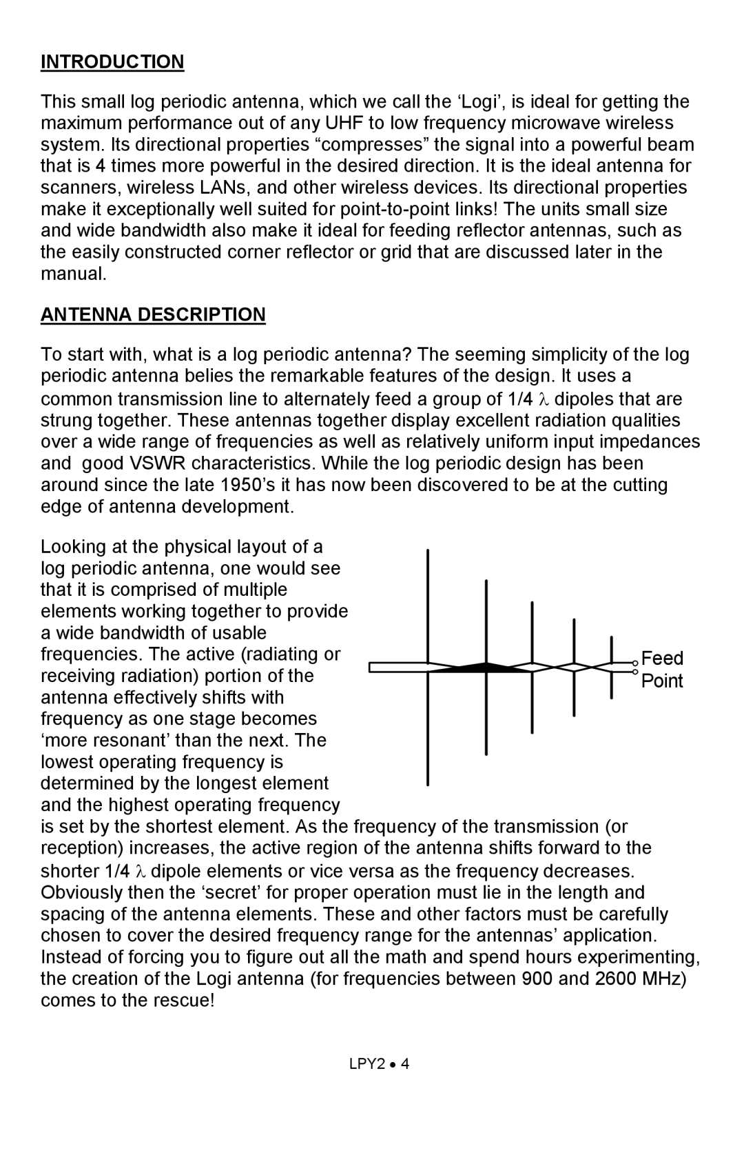
Looking at the physical layout of a log periodic antenna, one would see that it is comprised of multiple elements working together to provide a wide bandwidth of usable frequencies. The active (radiating or
receiving radiation) portion of the antenna effectively shifts with
frequency as one stage becomes ‘more resonant’ than the next. The lowest operating frequency is determined by the longest element and the highest operating frequency
is set by the shortest element. As the frequency of the transmission (or reception) increases, the active region of the antenna shifts forward to the shorter 1/4 λ dipole elements or vice versa as the frequency decreases. Obviously then the ‘secret’ for proper operation must lie in the length and spacing of the antenna elements. These and other factors must be carefully chosen to cover the desired frequency range for the antennas’ application. Instead of forcing you to figure out all the math and spend hours experimenting, the creation of the Logi antenna (for frequencies between 900 and 2600 MHz) comes to the rescue!
LPY2 • 4
