15. Install Q2, infrared phototransistor [black T1 case], to the left of D2. Make sure the flat spot faces the inside of the board. Let Q2 stick up 3/8” above the board.
Total Length: 2 1/4"
Feet
Runner
Top of Board
Runner
Total Length 1 3/4"
Total Length: 2 1/4"
Feet
Runner
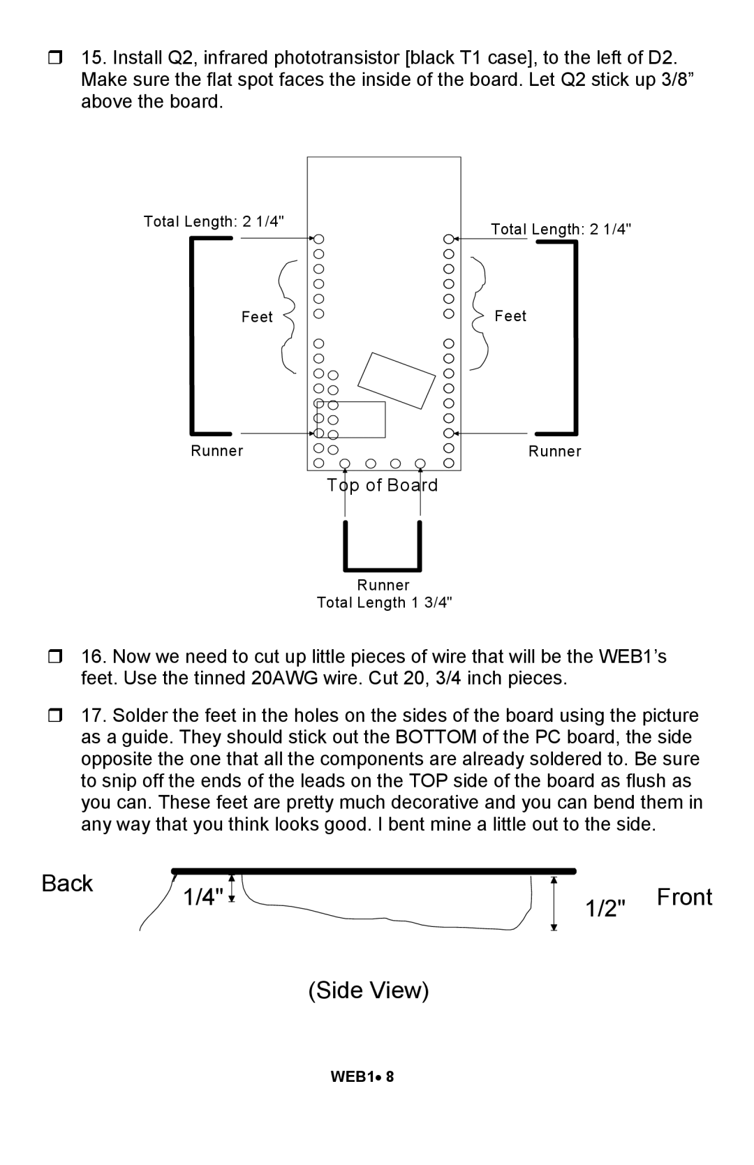
16. Now we need to cut up little pieces of wire that will be the WEB1’s feet. Use the tinned 20AWG wire. Cut 20, 3/4 inch pieces.
17. Solder the feet in the holes on the sides of the board using the picture as a guide. They should stick out the BOTTOM of the PC board, the side opposite the one that all the components are already soldered to. Be sure to snip off the ends of the leads on the TOP side of the board as flush as you can. These feet are pretty much decorative and you can bend them in any way that you think looks good. I bent mine a little out to the side.
Back | 1/4" |
|
1/2" Front
(Side View)
WEB1• 8