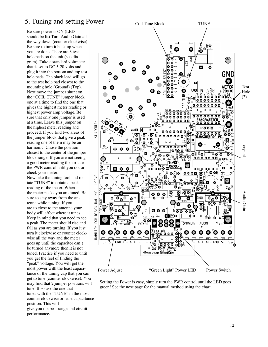
5. Tuning and setting Power | Coil Tune Block | TUNE |
Be sure power is ON (LED should be lit) Turn Audio Gain all the way down (counter clockwise) Be sure to turn it back up when you are done. There are 3 test hole pads on the unit (see dia- gram). Take a standard voltmeter that is set to DC
Now take the tuning tool and ro- tate “TUNE” to obtain a peak reading of the meter. When
the meter peaks you are tuned. Be sure to stay away from the an- tenna while tuning. If you
are to close to the antenna your body will affect where it tunes. Keep in mind that you need to see a peak. The meter should rise and fall as you are turning. If you just turn it clockwise or counter clock- wise all the way and the meter goes up until the capacitor can’t be turned anymore then it is not tuned. Practice if you need to until you get the feel of finding the “peak” voltage. You will get the most power with the least capaci- tance of the tuning cap that you can get to tune (counter clockwise). You may find that 2 jumper positions will tune. If so use the one that
tunes with the “TUNE” in the most counter clockwise or least capacitance position. This will
give you the best range and circuit performance.
Power Adjust | “Green Light” Power LED | Power Switch |
Setting the Power is easy, simply turn the PWR control until the LED goes green! See the next page for the manual method using the chart.
Test Hole
(3)
crystal
Audio Gain
12