PLUMBING FOR WATER CONNECTIONS

LOCATION

The VERSA heater requires water flow and positive pressure to fire and operate properly. It must therefore be installed downstream of the discharge side of the filter pump. A typical installation is plumbed as follows:

1.The inlet side of the filter is plumbed directly to the discharge side of the filter pump;

2.The outlet side of the filter is then plumbed to the inlet of the heater; and

3.The outlet of the heater is plumbed to the return line to the pool or spa. The pump, filter and heater are thus plumbed in series.

Plumbing from the heater back to the pool must not have any valves or restriction that could prevent flow when the pump is operating. To do so will void the warranty.

FLOW RATES

MIN.GPM: 20, MAX.GPM: 115*

*When flow rates exceed 115 GPM an external auxiliary bypass valve is required. See External auxiliary bypass valve section for details.

NOTE: High chemical concentration from feeders and chlorinators that are out of adjustment will cause very rapid corrosion to the heat exchanger in the heaters. Such damage is not covered under the warranty.

INTERNAL AUTOMATIC BY-PASS VALVE

A built-in automatic by-pass valve is provided in the in/out header. The internal by-pass valve automatically responds to changes in water pressure in the piping system. Proper amount of water flow is maintained through the heater under varying pressures dictated by the conditions of the pump and filter.

Fig. # 8078.0

CASTIRONHEADER

The inlet/outlet header accepts a 1-1/2" pipe thread. The header will accept either copper and galvanized pipe or CPVC adapters.

CAUTION: Never install PVC directly in header flanges. The initial connection must be made with a higher temperature material such as CPVC or Copper. PVC may be utilized immediately after the initial connection.

INLET/OUTLETHEADER

EXTERNAL AUXILIARY BYPASS VALVE (Where required)

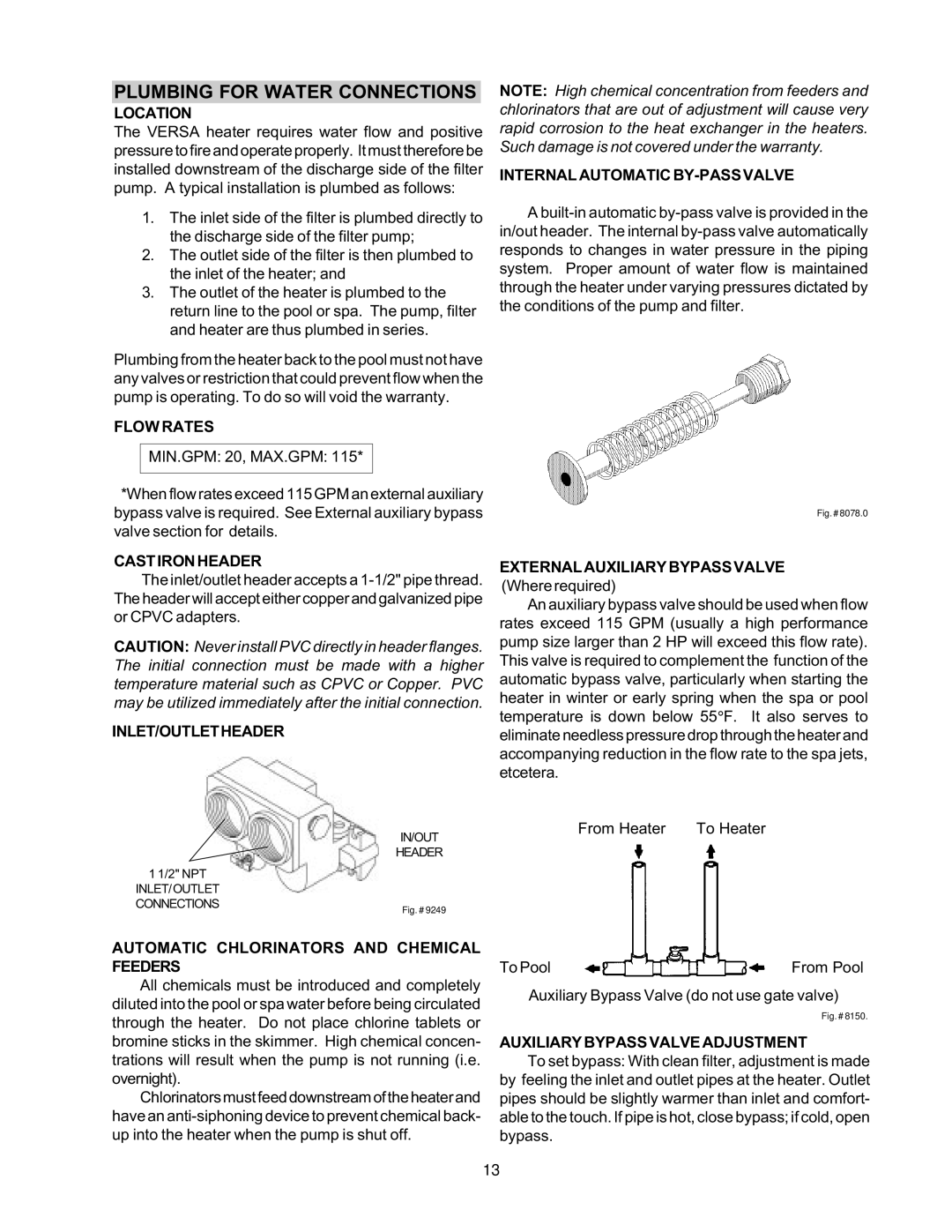
An auxiliary bypass valve should be used when flow rates exceed 115 GPM (usually a high performance pump size larger than 2 HP will exceed this flow rate). This valve is required to complement the function of the automatic bypass valve, particularly when starting the heater in winter or early spring when the spa or pool temperature is down below 55°F. It also serves to eliminate needless pressure drop through the heater and accompanying reduction in the flow rate to the spa jets, etcetera.

IN/OUT

HEADER

1 1/2" NPT

INLET/OUTLET CONNECTIONS

Fig. # 9249

From Heater To Heater

AUTOMATIC CHLORINATORS AND CHEMICAL FEEDERS

All chemicals must be introduced and completely diluted into the pool or spa water before being circulated through the heater. Do not place chlorine tablets or bromine sticks in the skimmer. High chemical concen- trations will result when the pump is not running (i.e. overnight).

Chlorinatorsmustfeeddownstreamoftheheaterand have an anti-siphoning device to prevent chemical back- up into the heater when the pump is shut off.

To Pool

From Pool

Auxiliary Bypass Valve (do not use gate valve)

Fig. # 8150.

AUXILIARY BYPASS VALVE ADJUSTMENT

To set bypass: With clean filter, adjustment is made by feeling the inlet and outlet pipes at the heater. Outlet pipes should be slightly warmer than inlet and comfort- able to the touch. If pipe is hot, close bypass; if cold, open bypass.

13

Page 14
Image 14
Raypak 105B installation instructions Plumbing for Water Connections

105B specifications

Raypak 105B is a well-engineered boiler designed for various heating applications. Known for its efficiency and reliability, the Raypak 105B is a preferred choice among professionals in both residential and commercial settings.

One of the main features of the Raypak 105B is its compact design. Measuring in at a size that allows for easy installation, it is ideal for locations where space is at a premium. The unit's lightweight materials contribute to a reduced load on structural components of buildings, making it an efficient option for retrofits and new installations alike.

The Raypak 105B operates on advanced technology that ensures optimal performance and energy efficiency. The unit boasts a high thermal efficiency rating, which translates to lower operational costs for users. Its innovative control system monitors and adjusts the heating output, ensuring that the boiler operates at peak efficiency while maintaining comfort.

Another significant characteristic of the Raypak 105B is its built-in hydrostat. This feature automatically controls water temperature, providing a safeguard against overheating and improving overall safety. The unit's durable stainless steel heat exchanger enhances the longevity of the product while also resisting corrosion, a common issue in boiler systems.

In terms of environmental considerations, the Raypak 105B is designed to meet or exceed industry standards for emissions. This not only helps users comply with regulations but also contributes to a reduced carbon footprint. Additionally, the natural gas or propane options add versatility in terms of fuel choice, catering to a wide range of applications.

Ease of maintenance is another advantage offered by the Raypak 105B. The unit is designed to provide straightforward access to key components, minimizing operational downtime when servicing is needed. This thoughtful design element supports both residential and commercial needs, ensuring reliability in various settings.

In summary, the Raypak 105B stands out due to its compact design, high thermal efficiency, advanced control systems, and robust safety features. With its focus on longevity, ease of maintenance, and environmental compliance, the Raypak 105B continues to be a leading choice for efficient heating solutions in diverse applications. Its reputation for reliability makes it a trusted option for those in need of dependable heating solutions.