Receiving Equipment
On receiving your equipment, check the carton visual- ly for external damage. If the carton is damaged, make a note on the Bill of Lading when signing for the equip- ment. Remove the complete assembly from the carton if it is damaged, and report the damage to the carrier immediately. Be sure that you receive the number of packages indicated on the Bill of Lading. Claims for shortages and damages must be filed with the carrier by consignee.
Purchased parts are subject to replacement only under the manufacturer's warranty. Debits for defec- tive replacement parts will not be accepted and defective parts will be replaced in kind only per our standard warranties.
When ordering parts, you must specify Model and Serial Number of the unit. When ordering under war- ranty conditions , you must also specify date of Installation.
Raypak recommends that this manual be reviewed thoroughly before installing the
THIS MANUAL SHOULD BE MAINTAINED IN LEGI- BLE CONDITION AND KEPT ADJACENT TO THE UNIT.
General Specifications
The
The Power Vent Assembly is a fan assisted combus- tion system designed for application to Raypak Heater Models
The
NOTE: The
4
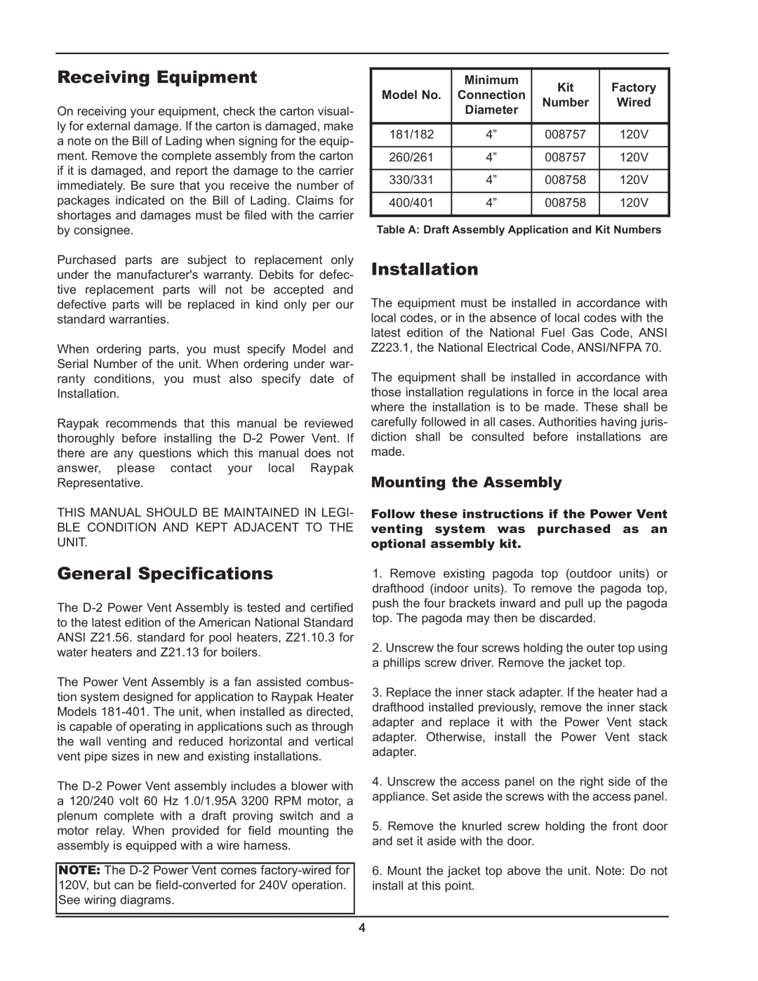
Model No. | Minimum | Kit | Factory |
Connection | |||
| Diameter | Number | Wired |
181/182 | 4” | 008757 | 120V |
260/261 | 4” | 008757 | 120V |
330/331 | 4” | 008758 | 120V |
400/401 | 4” | 008758 | 120V |
Table A: Draft Assembly Application and Kit Numbers
Installation
The equipment must be installed in accordance with local codes, or in the absence of local codes with the latest edition of the National Fuel Gas Code, ANSI Z223.1, the National Electrical Code, ANSI/NFPA 70. The equipment shall be installed in accordance with those installation regulations in force in the local area where the installation is to be made. These shall be carefully followed in all cases. Authorities having juris- diction shall be consulted before installations are made.
Mounting the Assembly
Follow these instructions if the Power Vent venting system was purchased as an optional assembly kit.
1.Remove existing pagoda top (outdoor units) or drafthood (indoor units). To remove the pagoda top, push the four brackets inward and pull up the pagoda top. The pagoda may then be discarded.
2.Unscrew the four screws holding the outer top using a phillips screw driver. Remove the jacket top.
3.Replace the inner stack adapter. If the heater had a drafthood installed previously, remove the inner stack adapter and replace it with the Power Vent stack adapter. Otherwise, install the Power Vent stack adapter.
4.Unscrew the access panel on the right side of the appliance. Set aside the screws with the access panel.
5.Remove the knurled screw holding the front door and set it aside with the door.
6.Mount the jacket top above the unit. Note: Do not install at this point.