Tools required
Electric or Portable Drill
3 mm (1/8”) Drill Bit and Stud Finder for Drywall Installation
8 mm (5/16”) Masonry Bit for Concrete Installation
Level
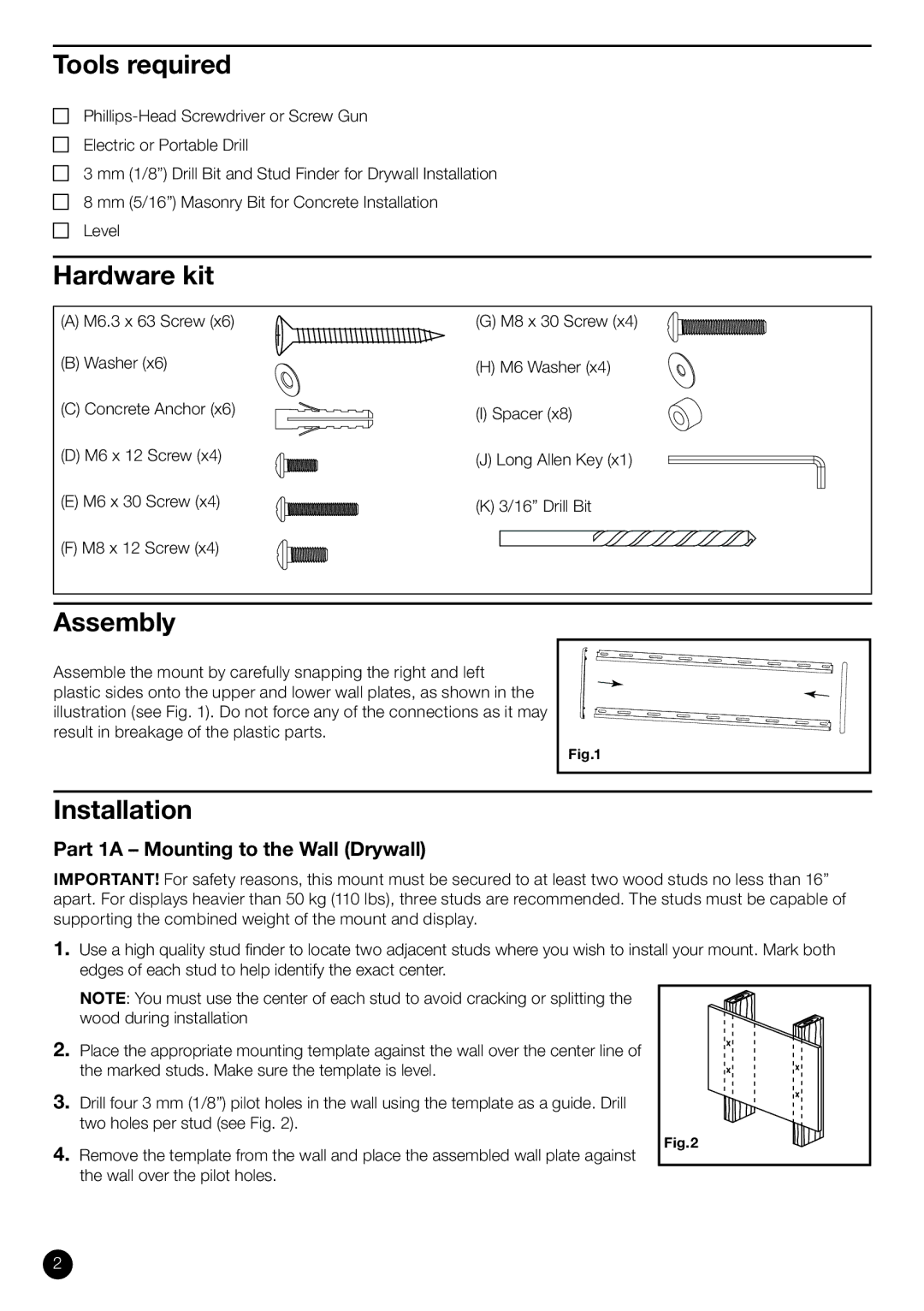
Hardware kit
(A) M6.3 x 63 Screw (x6) | (G) M8 x 30 Screw (x4) |
(B) Washer (x6) | (H) M6 Washer (x4) |
(C) Concrete Anchor (x6) | (I) Spacer (x8) |
(D) M6 x 12 Screw (x4) | (J) Long Allen Key (x1) |
(E) M6 x 30 Screw (x4) | (K) 3/16” Drill Bit |
(F) M8 x 12 Screw (x4) |
|
Assembly |
|
Assemble the mount by carefully snapping the right and left plastic sides onto the upper and lower wall plates, as shown in the illustration (see Fig. 1). Do not force any of the connections as it may result in breakage of the plastic parts.
Fig.1 |
Installation
Part 1A – Mounting to the Wall (Drywall)
IMPORTANT! For safety reasons, this mount must be secured to at least two wood studs no less than 16” apart. For displays heavier than 50 kg (110 lbs), three studs are recommended. The studs must be capable of supporting the combined weight of the mount and display.
1.Use a high quality stud fi nder to locate two adjacent studs where you wish to install your mount. Mark both edges of each stud to help identify the exact center.
NOTE: You must use the center of each stud to avoid cracking or splitting the wood during installation
2.Place the appropriate mounting template against the wall over the center line of the marked studs. Make sure the template is level.
3.Drill four 3 mm (1/8”) pilot holes in the wall using the template as a guide. Drill two holes per stud (see Fig. 2).
4.Remove the template from the wall and place the assembled wall plate against the wall over the pilot holes.
Fig.2
2